DISASSEMBLY
Removal / installation
| 1. REMOVE REAR DIFFERENTIAL BREATHER PLUG |

Remove the breather plug from the differential carrier cover.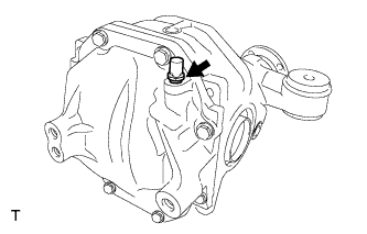

| 2. REMOVE REAR DIFFERENTIAL CARRIER COVER |
Remove the 8 bolts from the differential carrier cover.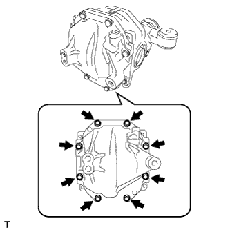
Using a brass bar and hammer, lightly tap the rib of the side bearing retainer to remove it.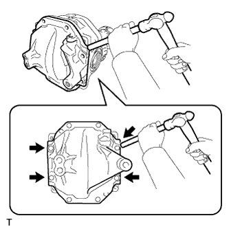
- NOTICE:
- Do not damage the sealing surface of the differential carrier.
| 3. REMOVE REAR DIFFERENTIAL BREATHER PLUG OIL DEFLECTOR |
Remove the bolt and oil deflector from the differential carrier cover.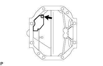
| 4. SECURE REAR DIFFERENTIAL CARRIER |
Set the differential carrier to an overhaul stand, etc., as shown in the illustration.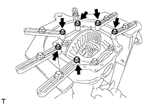
| 5. INSPECT RUNOUT OF DIFFERENTIAL RING GEAR |
Using a dial indicator, measure the runout of the ring gear.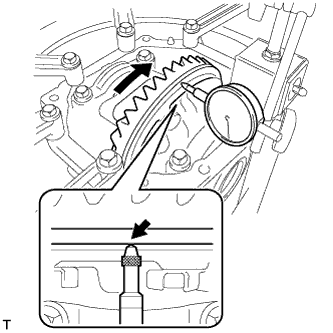
- Maximum runout:
- 0.07 mm (0.0028 in.)
| 6. INSPECT DIFFERENTIAL RING GEAR BACKLASH |
Set the dial indicator perpendicular to the end of the ring gear face.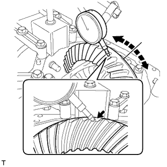
While holding the rear drive pinion companion flange, rotate the ring gear and measure the backlash.
- Backlash:
- 0.13 to 0.18 mm (0.0051 to 0.0071 in.)
- HINT:
- Record the measured backlash to use as a reference for selecting a side gear shaft plate washer.
- Inspect tooth contact to use the result as a reference for selecting a side gear shaft plate washer.
- Record the measured backlash to use as a reference for selecting a side gear shaft plate washer.
Select a side gear shaft plate washer that will set ring gear backlash within the specified range, and install it to the ring gear back side.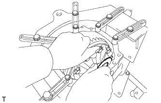
Washer thickness Thickness mm (in.)
Thickness mm (in.)
Thickness mm (in.)
2.57 to 2.59 (0.1012 to 0.1020)
2.89 to 2.91 (0.1138 to 0.1146)
3.21 to 3.23 (0.1264 to 0.1271)
2.59 to 2.61 (0.1020 to 0.1028)
2.91 to 2.93 (0.1146 to 0.1154)
3.23 to 3.25 (0.1271 to 0.1280)
2.61 to 2.63 (0.1028 to 0.1035)
2.93 to 2.95 (0.1154 to 0.1161)
3.25 to 3.27 (0.1280 to 0.1287)
2.63 to 2.65 (0.1035 to 0.1043)
2.95 to 2.97 (0.1161 to 0.1169)
3.27 to 3.29 (0.1287 to 0.1295)
2.65 to 2.67 (0.1043 to 0.1051)
2.97 to 2.99 (0.1169 to 0.1177)
3.29 to 3.31 (0.1295 to 0.1303)
2.67 to 2.69 (0.1051 to 0.1059)
2.99 to 3.01 (0.1177 to 0.1185)
3.31 to 3.33 (0.1303 to 0.1311)
2.69 to 2.71 (0.1059 to 0.1067)
3.01 to 3.03 (0.1185 to 0.1193)
3.33 to 3.35 (0.1311 to 0.1319)
2.71 to 2.73 (0.1067 to 0.1075)
3.03 to 3.05 (0.1193 to 0.1201)
3.35 to 3.37 (0.1319 to 0.1327)
2.73 to 2.75 (0.1075 to 0.1083)
3.05 to 3.07 (0.1201 to 0.1209)
3.37 to 3.39 (0.1327 to 0.1335)
2.75 to 2.77 (0.1083 to 0.1091)
3.07 to 3.09 (0.1209 to 0.1217)
3.39 to 3.41 (0.1335 to 0.1343)
2.77 to 2.79 (0.1091 to 0.1098)
3.09 to 3.11 (0.1217 to 0.1224)
3.41 to 3.43 (0.1343 to 0.1350)
2.79 to 2.81 (0.1098 to 0.1106)
3.11 to 3.13 (0.1224 to 0.1232)
3.43 to 3.45 (0.1350 to 0.1358)
2.81 to 2.83 (0.1106 to 0.1114)
3.13 to 3.15 (0.1232 to 0.1240)
3.45 to 3.47 (0.1358 to 0.1366)
2.83 to 2.85 (0.1114 to 0.1122)
3.15 to 3.17 (0.1240 to 0.1248)
3.47 to 3.49 (0.1366 to 0.1374)
2.85 to 2.87 (0.1122 to 0.1130)
3.17 to 3.19 (0.1248 to 0.1256)
-
2.87 to 2.89 (0.1130 to 0.1138)
3.19 to 3.21 (0.1256 to 0.1264)
-
Make the differential case bearing and side gear shaft plate washer snug by tapping on the ring gear with a plastic hammer.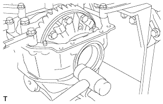
Set the dial indicator perpendicular to the end of the ring gear face.
While holding the rear drive pinion companion flange rear, rotate the ring gear and measure the backlash.
- Backlash:
- 0.13 to 0.18 mm (0.0051 to 0.0071 in.)
If the backlash is not within the specified range, select a side gear shaft plate washer that will set the ring gear backlash within the specified range and install it into the ring gear back side.
Select a thicker side gear shaft plate washer so that the clearance between the case bearing outer race end on the ring gear teeth side and the carrier becomes zero or close to zero.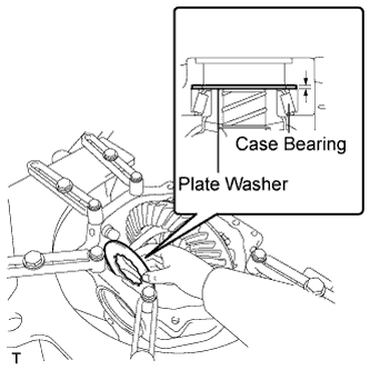
Make the differential case bearing and side gear shaft plate washer snug by tapping on the ring gear with a plastic hammer.
Set the dial indicator perpendicular to the end of the ring gear face.
While holding the rear drive pinion companion flange, rotate the ring gear and measure the backlash.
- Backlash:
- 0.13 to 0.18 mm (0.0051 to 0.0071 in.)
| 7. INSPECT TOOTH CONTACT BETWEEN RING GEAR AND DRIVE PINION |
Coat 3 or 4 teeth at 3 different positions on the ring gear with red lead primer.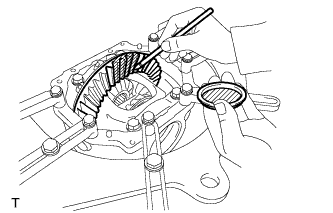
Rotate the ring gear in both directions.
Inspect the tooth contact pattern.
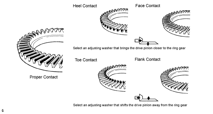
If the teeth are not contacting properly, use the following table to select a proper washer for correction.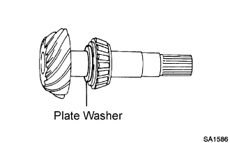
- NOTICE:
- If the contact pattern is face contact or flank contact, tooth contact may be adjustable while keeping the backlash within the specified range.
- If the thickness of the drive pinion washer has been changed, adjust the backlash and measure the total preload.
- If the contact pattern is face contact or flank contact, tooth contact may be adjustable while keeping the backlash within the specified range.
Washer thickness: Thickness mm (in.)
Thickness mm (in.)
Thickness mm (in.)
1.69 to 1.71 (0.0665 to 0.0673)
1.93 to 1.95 (0.0760 to 0.0768)
2.17 to 2.19 (0.0854 to 0.0862)
1.72 to 1.74 (0.0677 to 0.0685)
1.96 to 1.98 (0.0772 to 0.0780)
2.20 to 2.22 (0.0866 to 0.0874)
1.75 to 1.77 (0.0688 to 0.0697)
1.99 to 2.01 (0.0783 to 0.0791)
2.23 to 2.25 (0.0878 to 0.0886)
1.78 to 1.80 (0.0701 to 0.0709)
2.02 to 2.04 (0.0795 to 0.0803)
2.26 to 2.28 (0.0890 to 0.0898)
1.81 to 1.83 (0.0713 to 0.0720)
2.05 to 2.07 (0.0807 to 0.0815)
2.29 to 2.31 (0.0902 to 0.0909)
1.84 to 1.86 (0.0724 to 0.0732)
2.08 to 2.10 (0.0819 to 0.0827)
2.32 to 2.34 (0.0913 to 0.0921)
1.87 to 1.89 (0.0736 to 0.0744)
2.11 to 2.13 (0.0831 to 0.0839)
-
1.90 to 1.92 (0.0748 to 0.0756)
2.14 to 2.16 (0.0843 to 0.0850)
-
| 8. INSPECT RUNOUT OF REAR DRIVE PINION COMPANION FLANGE |
Using a dial indicator, measure the runout of the companion flange vertically and horizontally.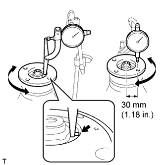
- Maximum runout:
- 0.09 mm (0.0035 in.)
| 9. INSPECT DIFFERENTIAL DRIVE PINION PRELOAD |
Using a torque wrench, measure the preload of the drive pinion.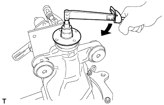
- Preload (at starting):
Specifications
Drive pinion preload
New bearing
1.49 to 2.59 N*m (15.2 to 26.4 kgf*cm, 13.2 to 22.9 in.*lbf)
Reused bearing
1.11 to 1.91 N*m (11.3 to 19.5 kgf*cm, 9.8 to 16.9 in.*lbf)
| 10. INSPECT TOTAL PRELOAD |
Using a torque wrench, measure the preload with the teeth of the drive pinion and ring gear in contact.
- Preload (at starting):
Specifications
New drive pinion tapered roller bearing
Reused drive pinion tapered roller bearing
New differential case bearing
2.57 to 4.26 N*m (26.2 to 43.4 kgf*cm, 22.7 to 37.7 in.*lbf)
2.19 to 3.58 N*m (22.3 to 36.5 kgf*cm, 19.4 to 31.7 in.*lbf)
Reused differential case bearing
1.98 to 3.37 N*m (20.2 to 34.4 kgf*cm, 17.5 to 29.8 in.*lbf)
1.60 to 2.69 N*m (16.3 to 27.4 kgf*cm, 14.2 to 23.8 in.*lbf)
| 11. REMOVE REAR DIFFERENTIAL SIDE GEAR SHAFT OIL SEAL |
Using SST, remove the 2 oil seals.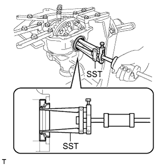
- SST
- 09308-00010
| 12. REMOVE REAR DRIVE PINION NUT |
Using SST and a hammer, unstake the staked part of the drive pinion nut.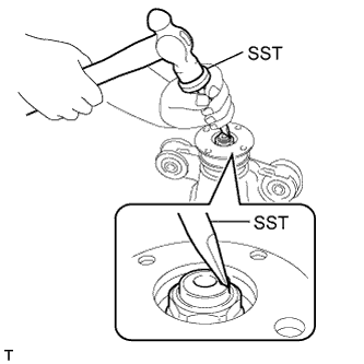
- SST
- 09930-00010
- NOTICE:
- Be sure to use SST with the tapered surface facing the shaft.
- Do not grind the tip of the SST with a grinder, etc.
- Completely loosen the staked part of the nut when removing it.
- Do not damage the threads of the drive pinion.
- Be sure to use SST with the tapered surface facing the shaft.
Using SST to hold the flange, remove the drive pinion nut.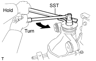
- SST
- 09330-00021
| 13. REMOVE REAR DRIVE PINION COMPANION FLANGE |
Using SST, remove the companion flange.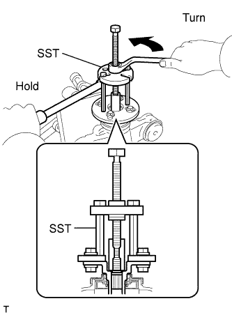
- SST
- 09950-30012
(09951-03010, 09953-03010, 09954-03010, 09955-03030, 09956-03030)
- NOTICE:
- Apply grease to the threads and tip of the SST center bolt before use.
| 14. REMOVE REAR DIFFERENTIAL DUST DEFLECTOR |
- HINT:
- Perform this procedure only when the dust deflector is damaged.
Using SST and a press, remove the dust deflector.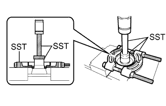
- SST
- 09950-00020
09950-60010 (09951-00380)
09950-70010 (09951-07100)
- NOTICE:
- Do not drop the companion flange.
| 15. REMOVE REAR DIFFERENTIAL CARRIER OIL SEAL |
Using SST, remove the oil seal from the differential carrier.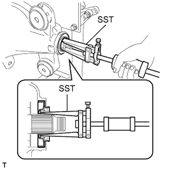
- SST
- 09308-00010
| 16. REMOVE REAR DIFFERENTIAL DRIVE PINION OIL SLINGER |
Remove the drive pinion oil slinger.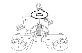
| 17. REMOVE REAR DRIVE PINION FRONT TAPERED ROLLER BEARING |
Using SST, remove the inner race of the rear drive pinion front tapered roller bearing from the drive pinion.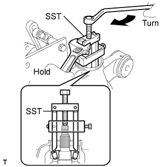
- SST
- 09556-22010
- NOTICE:
- Apply grease to the threads and tip of the SST center bolt before use.
| 18. REMOVE REAR DIFFERENTIAL DRIVE PINION BEARING SPACER |
Remove the drive pinion bearing spacer.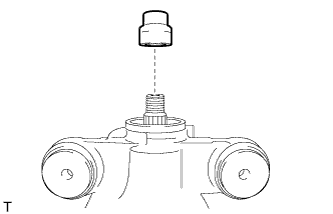
| 19. REMOVE DIFFERENTIAL CASE ASSEMBLY |
Put matchmarks on either set of the bearing cap and differential carrier.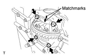
Remove the 4 bolts and 2 bearing caps.
- NOTICE:
- Do not swap bearing caps, as each cap is only suitable for its original location and installation direction on the carrier it was manufactured on.
Using SST and a hammer, remove the 2 side gear shaft plate washers.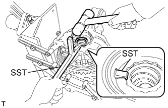
- SST
- 09504-22011
- NOTICE:
- Put identification marks on the side gear shaft plate washer to show the location for installation (back side or teeth side), or keep them separate so that they can be distinguished.
- HINT:
- Measure the thickness of the plate washers and note it.
Remove the differential case assembly and the case bearing outer races LH and RH from the differential carrier.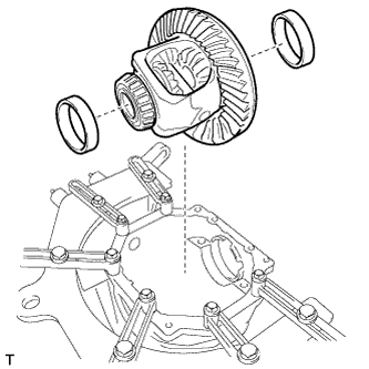
- NOTICE:
- Do not damage the differential case bearing or ring gear.
- Put identification marks on the case bearing outer race to show the location for installation (back side or teeth side), or keep them separate so that they can be distinguished.
- Do not damage the differential case bearing or ring gear.
| 20. REMOVE REAR DRIVE PINION REAR TAPERED ROLLER BEARING |
Remove the drive pinion from the differential carrier.
Using SST and a press, remove the inner race of the rear drive pinion rear tapered roller bearing from the drive pinion.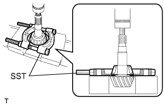
- SST
- 09950-00020
- NOTICE:
- Do not drop the drive pinion.
- HINT:
- If either the drive pinion or ring gear is damaged, replace both as a set.
Remove the drive pinion plate washer from the drive pinion.
- HINT:
- Measure the thickness of the plate washer and note it.
Using a brass bar and a hammer, remove the outer race of the rear drive pinion front tapered roller bearing from the differential carrier.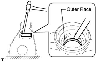
- NOTICE:
- Place the brass bar onto the outer race of the rear drive pinion front tapered roller bearing. Do not damage the differential carrier.
| 21. REMOVE REAR DRIVE PINION REAR TAPERED ROLLER BEARING |
Using a brass bar and a hammer, remove the outer race of the rear drive pinion rear tapered roller bearing from the differential carrier.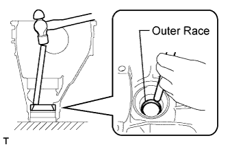
- NOTICE:
- Place the brass bar onto the outer race of the rear drive pinion front tapered roller bearing. Do not damage the differential carrier.
| 22. REMOVE DIFFERENTIAL RING GEAR |
Hold the differential case in a vise between aluminum plates.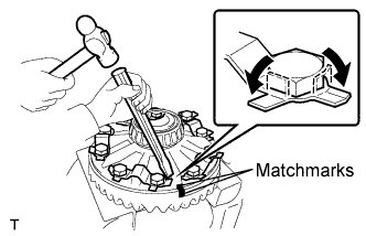
- NOTICE:
- Do not overtighten the vise.
Put matchmarks on the ring gear and differential case.
Using a chisel and a hammer, unstake the 5 lock plates.
Remove the 10 ring gear set bolts and 5 lock plates.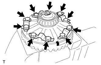
Using a plastic hammer, tap on the ring gear to separate it from the differential case.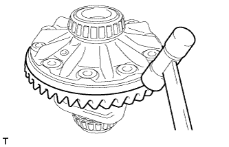
- HINT:
- Use cloth to prevent damage to the ring gear teeth.
| 23. INSPECT RUNOUT OF DIFFERENTIAL CASE ASSEMBLY |
- HINT:
- Perform this procedure only when the runout of the differential ring gear exceeds the specified maximum value.
Install the case bearing outer races LH and RH to the case bearing inner races LH and RH respectively.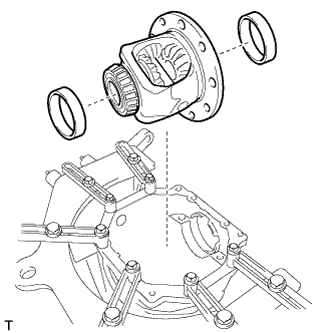
- NOTICE:
- Be sure to install the bearing outer races in each correct position.
- Do not damage the differential case bearing or ring gear.
- Be sure to install the bearing outer races in each correct position.
Install the differential case to the differential carrier.
Install the right and left (back side and teeth side) side gear shaft plate washers so that there is no looseness on the case bearings.
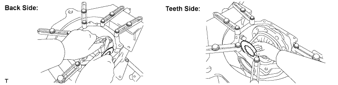
Align the matchmarks on the bearing cap and differential carrier, and install the 2 bearing caps.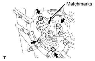
- NOTICE:
- Make sure that the right and left bearing caps are not interchanged.
Tighten both bearing caps with the 4 bolts.
- Torque:
- 85 N*m{ 870 kgf*cm , 63 ft.*lbf }
Using a dial indicator, measure the differential case runout.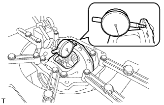
- Maximum case runout:
- 0.07 mm (0.0028 in.)
Remove the 4 bolts and 2 bearing caps.
- NOTICE:
- Do not swap bearing caps, as each cap is only suitable for its original location and installation direction on the carrier it was manufactured on.
Remove the right and left bearing caps, 2 side gear shaft plate washers and differential case.
- NOTICE:
- Do not damage the differential case bearing or ring gear.
| 24. REMOVE REAR DIFFERENTIAL CASE BEARING |
- HINT:
- Perform this procedure only when replacing the case bearing or differential case.
Hold the differential case in a vise between aluminum plates.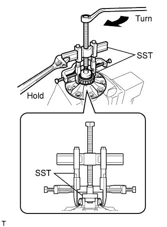
- NOTICE:
- Do not overtighten the vise.
Using SST, remove the case bearing inner races LH and RH from the differential case.
- SST
- 09950-40011
(09951-04020, 09952-04010, 09953-04030, 09954-04010, 09955-04061, 09957-04010, 09958-04011)
09950-60010 (09951-00480, 09951-00350, 09952-06010)
- NOTICE:
- Do not deform the bearing cage if the bearing is to be reused.
- Hook the SST claw from the dent of the differential case to the bearing inner race.
- Apply grease to the threads and tip of the SST center bolt before use.
- Do not deform the bearing cage if the bearing is to be reused.