Washer Motor Circuit
Circuit diagnosis
DESCRIPTION
The front controller receives washer switch condition (on or off) information from the windshield wiper switch assembly, and operates the WASH relay.WIRING DIAGRAM
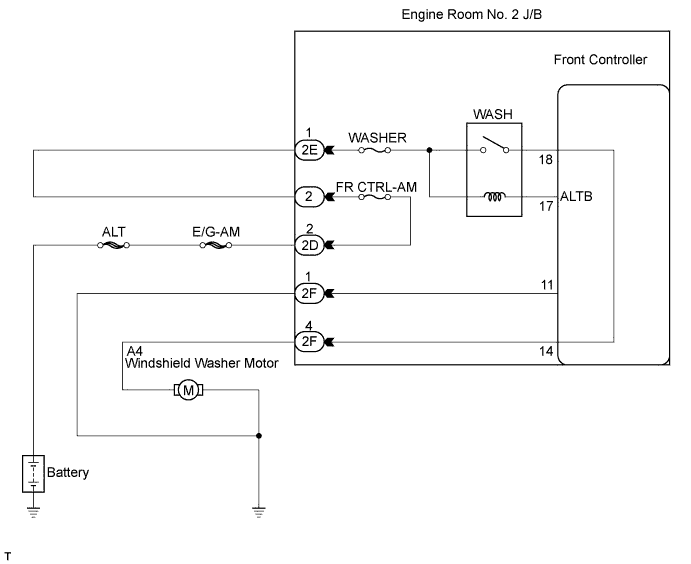

INSPECTION PROCEDURE
| 1. PERFORM ACTIVE TEST USING INTELLIGENT TESTER (WASHER MOTOR) |

Connect the intelligent tester to the DLC3.
Turn the engine switch on (IG) and turn the intelligent tester main switch on.
Select the item below in the ACTIVE TEST and then check that the washer motor operates.
Body No. 5 (Front Controller): Item
Test Details
Diagnostic Note
Washer Motor Operation
Washer motor operation OFF / ON
-
- OK:
- Washer motor operates.
|
|
||||

| OK | ||
 |
||
| ||
| 2. CHECK ENGINE ROOM NO. 2 J/B (FRONT CONTROLLER - ENGINE ROOM NO. 2 J/B, BODY GROUND) |
Measure the voltage according to the value(s) in the table below with the connectors connected.
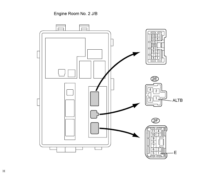
- Standard voltage:
Tester Connection
Condition
Specified Condition
2E-1 (ALTB) - 2F-1 (E)
Engine switch on (IG) and washer switch ON
10 to 14 V
Measure the resistance according to the value(s) in the table below.
- Standard resistance:
Tester Connection
Condition
Specified Condition
2F-1 (E) - Body ground
Always
Below 1 Ω
|
|
||||
| OK | |
 |
| 3. INSPECT WINDSHIELD WASHER MOTOR AND PUMP ASSEMBLY |
Disconnect the washer motor connector.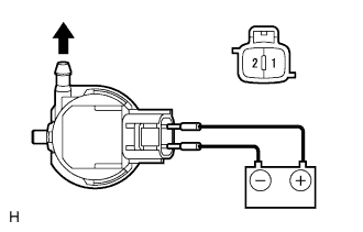
Connect the positive (+) battery lead to terminal 1 of the washer motor, and the negative (-) battery lead to terminal 2.
- OK:
- Washer motor operates.
|
|
||||

| OK | ||
|
||
| ||
| 4. CHECK HARNESS OR CONNECTOR (FRONT CONTROLLER - BODY GROUND) |
Measure the voltage according to the value(s) in the table below.
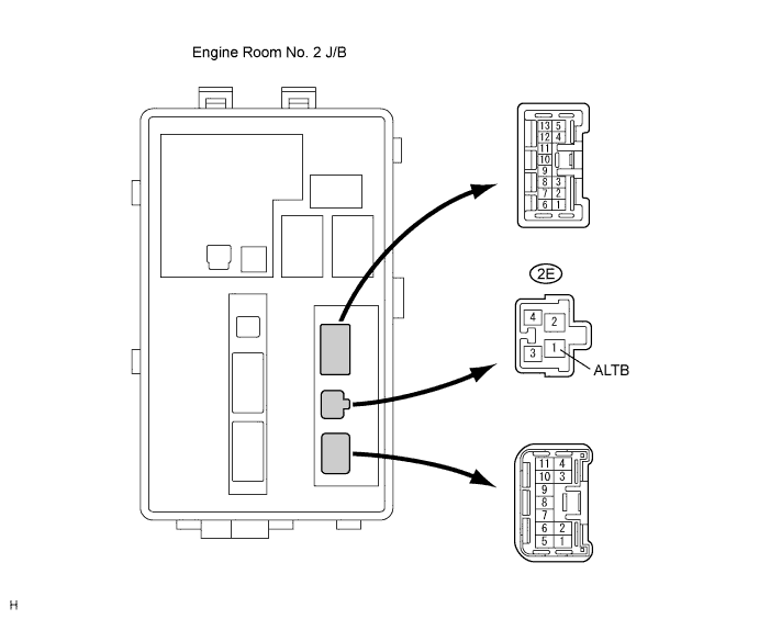
- Standard voltage:
Tester Connection
Condition
Specified Condition
2E-1 (ALTB) - Body ground
Always
10 to 14 V
|
|
||||
| OK | ||
|
||
| ||