Headlight Cleaner Motor and Relay Circuit
Circuit diagnosis
DESCRIPTION
This circuit provides power to the headlight cleaner control relay.The headlight cleaner control relay receives a signal from each switch and sends the signal to the headlight cleaner motor and pump assembly to operate it.
WIRING DIAGRAM
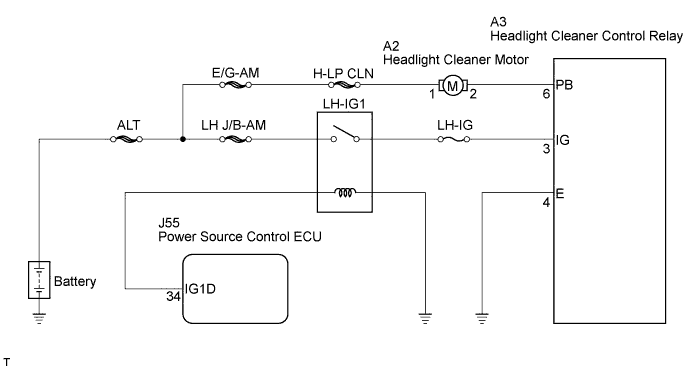

INSPECTION PROCEDURE
| 1. INSPECT HEADLIGHT CLEANER MOTOR AND PUMP ASSEMBLY |

Disconnect the connector from the headlight cleaner motor and pump assembly.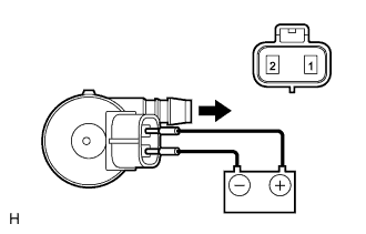
Connect the positive (+) battery lead to terminal 1 of the headlight cleaner motor and pump assembly, and the negative (-) battery lead to terminal 2.
- OK:
- Operation sounds are heard.
|
|
||||

| OK | |
 |
| 2. CHECK HARNESS AND CONNECTOR (HEADLIGHT CLEANER MOTOR CIRCUIT) |
Connect the headlight cleaner motor and pump assembly connector.
Disconnect the A3 headlight cleaner control relay connector.
Measure the voltage according to the value(s) in the table below.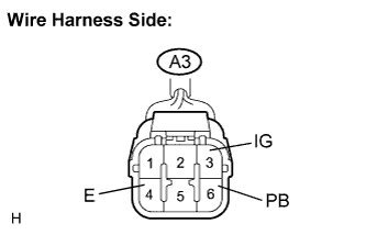
- Standard voltage:
Tester Connection
Condition
Specified Condition
A3-3 (IG) - A3-4 (E)
Engine switch off
Below 1 V
Engine switch on (IG)
10 to 14 V
A3-6 (PB) - A3-4 (E)
Always
10 to 14 V
|
|
||||
| OK | ||
 |
||
| ||