B1244
Diagnostic trouble codes
DESCRIPTION
This DTC is output when a failure of the automatic light control sensor circuit is detected.| DTC No. |
DTC Detection Condition |
Trouble Area |
| B1244 |
|
|
WIRING DIAGRAM
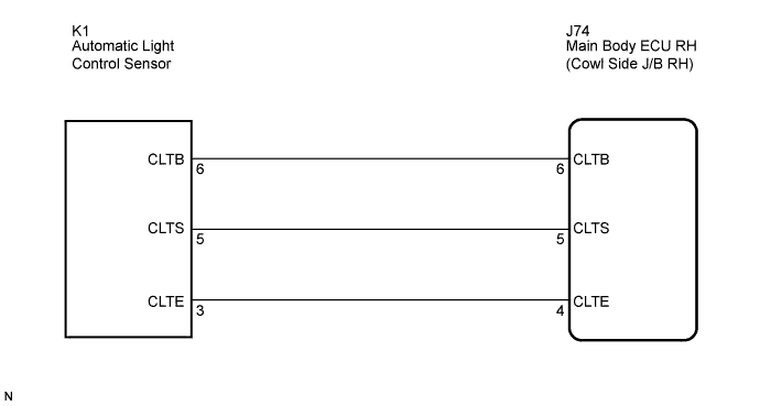

INSPECTION PROCEDURE
| 1. CHECK AUTOMATIC LIGHT CONTROL SENSOR (OPERATION) |

Connect the intelligent tester to the DLC3.
Turn the engine switch on (IG).
Turn the intelligent tester main switch on.
Select the "DATA LIST" on the intelligent tester.
DATA LIST: Main Body: (Main Body ECU RH) Item
Measurement Item / Display (Range)
Normal Condition
Illumination Rate Info
Illumination information / 10 to 99.99 ms
8 to 22 ms
The value of the illumination rate should change in the following range when light contacts the automatic light control sensor or when the automatic light control sensor is covered.
- OK:
- 8 to 22 ms
- HINT:
- This is the time taken for the automatic light control sensor to generate one cycle of frequency according to the brightness.
|
|
||||

| NG | |
 |
| 2. CHECK HARNESS AND CONNECTOR (MAIN BODY ECU RH - AUTOMATIC LIGHT CONTROL SENSOR) |
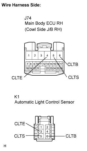 |
Disconnect the J74 main body ECU RH connector.
Disconnect the K1 automatic light control sensor connector.
Measure the resistance according to the value(s) in the table below.
- Standard resistance:
Tester Connection
Condition
Specified Condition
J74-6 (CLTB) - K1-6 (CLTB)
Always
Below 1 Ω
J74-5 (CLTS) - K1-5 (CLTS)
Always
Below 1 Ω
J74-4 (CLTE) - K1-3 (CLTE)
Always
Below 1 Ω
J74-6 (CLTB) - Body ground
Always
10 kΩ or higher
J74-5 (CLTS) - Body ground
Always
10 kΩ or higher
J74-4 (CLTE) - Body ground
Always
10 kΩ or higher
Connect the 2 connectors.
|
|
||||
| OK | |
|
| 3. CHECK AUTOMATIC LIGHT CONTROL SENSOR |
Disconnect the automatic light control sensor.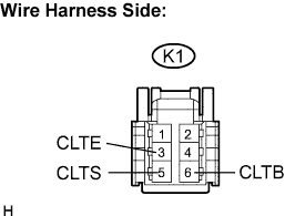
Measure the resistance according to the value(s) in the table below.
- Standard resistance:
Tester Connection
Condition
Specified Condition
K1-3 (CLTE) - Body ground
Always
Below 1 Ω
Connect the voltmeter's positive (+) lead to terminal 6 and the negative (-) lead to terminal 3.
Measure the voltage according to the value(s) in the table below.
- Standard voltage:
Tester Connection
Condition
Specified Condition
K1-3 (CLTE) - K1-6 (CLTB)
Engine switch on (IG)
10 to 14 V
Connect the K1 automatic light control sensor connector.
Connect the oscilloscope and check the waveform according the the table below.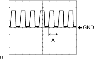
- Standard voltage:
Tester Connection
Condition
Specified Condition
Tester Range
K1-3 (CLTE) - K1-5 (CLTS)
Engine switch on (IG), Headlight dimmer switch in AUTO
Correct waveform is as shown
5 V Division, 5 msec/Division
|
|
||||
| OK | ||
 |
||
| ||