B2412
Diagnostic trouble codes
DESCRIPTION
The swivel actuator receives the signal from the AFS ECU to operate and sends the signal regarding the direction of the headlight and condition of the headlight swivel motor to the AFS ECU.| DTC No. |
DTC Detection Condition |
Trouble Area |
| B2412 |
|
|
| B2413 |
|
|
WIRING DIAGRAM
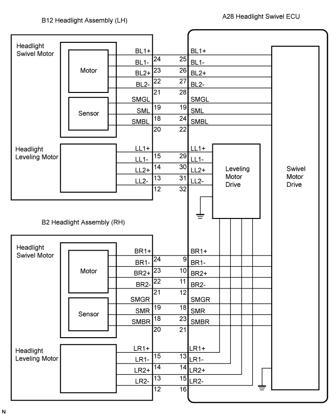

INSPECTION PROCEDURE
| 1. PERFORM ACTIVE TEST BY INTELLIGENT TESTER |

Connect the intelligent tester to the DLC3.
Turn the engine switch on (IG).
Turn the intelligent tester main switch on.
Select the "ACTIVE TEST" on the intelligent tester.
Check swivel motor operates with the intelligent tester.
ACTIVE TEST: AFS ECU Item
Test Details
Diagnostic Note
Drive Swivel Motor RH
Drive the swivel motor RIGHT / OFF
-
Drive Swivel Motor LH
Drive the swivel motor LEFT / OFF
-
- OK:
- Swivel motor operates.
- Result:
Result
Proceed to
OK (When checking from PROBLEM SYMPTOMS TABLE)
A
OK (When checking from DIAGNOSTIC TROUBLE CODE CHART)
B
NG
C
|
|
||||
|
|
||||


| A | ||
 |
||
| ||
| 2. INSPECT HEADLIGHT ASSEMBLY |
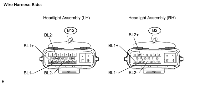
Disconnect the B12 and B2 headlight assembly connectors.
Measure the resistance according to the value(s) in the table below.
- Standard resistance:
- LH Side (B2412):
Tester Connection
Condition
Specified Condition
B12-23 (BL1-) - B12-24 (BL1+)
Always
6 to 8 Ω
B12-21 (BL2-) - B12-22 (BL2+)
Always
6 to 8 Ω
- RH Side (B2413):
Tester Connection
Condition
Specified Condition
B2-23 (BL1-) - B2-24 (BL1+)
Always
6 to 8 Ω
B2-22 (BL2-)- B2-21 (BL2+)
Always
6 to 8 Ω
- HINT:
- Measure the resistance after the headlight has cooled.
|
|
||||
| OK | |
 |
| 3. CHECK HARNESS AND CONNECTOR (HEADLIGHT ASSEMBLY - AFS ECU) |
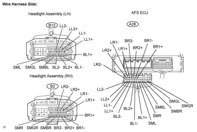
Disconnect the A28 AFS ECU connector.
Disconnect the B12 and B2 headlight connectors.
Measure the resistance according to the value(s) in the table below.
- Standard resistance:
- LH Side (B2412):
Tester Connection
Condition
Specified Condition
A28-25 (BL1+) - B12-24 (BL1+)
Always
Below 1 Ω
A28-26 (BL1-) - B12-23 (BL1-)
Always
Below 1 Ω
A28-27 (BL2+)- B12-22 (BL2+)
Always
Below 1 Ω
A28-28 (BL2-) - B12-21 (BL2-)
Always
Below 1 Ω
A28-19 (SMGL) - B12-19 (SMGL)
Always
Below 1 Ω
A28-24 (SML) - B12-18 (SML)
Always
Below 1 Ω
A28-22 (SMBL) - B12-20 (SMBL)
Always
Below 1 Ω
A28-29 (LL1+) - B12-15 (LL1+)
Always
Below 1 Ω
A28-30 (LL1-) - B12-14 (LL1-)
Always
Below 1 Ω
A28-31 (LL2+) - B12-13 (LL2+)
Always
Below 1 Ω
A28-32 (LL2-) - B12-12 (LL2-)
Always
Below 1 Ω
A28-25 (BL1+) - Body ground
Always
10 kΩ or higher
A28-26 (BL1-) - Body ground
Always
10 kΩ or higher
A28-27 (BL2+) - Body ground
Always
10 kΩ or higher
A28-28 (BL2-) - Body ground
Always
10 kΩ or higher
A28-19 (SMGL) - Body ground
Always
10 kΩ or higher
A28-24 (SML) - Body ground
Always
10 kΩ or higher
A28-22 (SMBL) - Body ground
Always
10 kΩ or higher
A28-29 (LL1+) - Body ground
Always
10 kΩ or higher
A28-30 (LL1-) - Body ground
Always
10 kΩ or higher
A28-31 (LL2+) - Body ground
Always
10 kΩ or higher
A28-32 (LL2-) - Body ground
Always
10 kΩ or higher
- RH Side (B2413):
Tester Connection
Condition
Specified Condition
A28-9 (BR1+) - B2-24 (BR1+)
Always
Below 1 Ω
A28-10 (BR1-) - B2-23 (BR1-)
Always
Below 1 Ω
A28-11 (BR2+) - B2-22 (BR2+)
Always
Below 1 Ω
A28-12 (BR2-) - B2-21 (BR2+)
Always
Below 1 Ω
A28-18 (SMGR) - B2-19 (SMGR)
Always
Below 1 Ω
A28-21 (SMBR) - B2-20 (SMR)
Always
Below 1 Ω
A28-23 (SMR) - B2-18 (SMBR)
Always
Below 1 Ω
A28-13 (LR1+) - B2-15 (LR1+)
Always
Below 1 Ω
A28-14 (LR1-) - B2-14 (LR1-)
Always
Below 1 Ω
A28-15 (LR2+) - B2-13 (LR2+)
Always
Below 1 Ω
A28-16 (LR2-) - B2-12 (LR2-)
Always
Below 1 Ω
A28-9 (BR1+) - Body ground
Always
10 kΩ or higher
A28-10 (BR1-) - Body ground
Always
10 kΩ or higher
A28-11 (BR2+) - Body ground
Always
10 kΩ or higher
A28-12 (BR2-) - Body ground
Always
10 kΩ or higher
A28-18 (SMGR) - Body ground
Always
10 kΩ or higher
A28-21 (SMBR) - Body ground
Always
10 kΩ or higher
A28-23 (SMR) - Body ground
Always
10 kΩ or higher
A28-13 (LR1+) - Body ground
Always
10 kΩ or higher
A28-14 (LR1-)- Body ground
Always
10 kΩ or higher
A28-15 (LR2+) - Body ground
Always
10 kΩ or higher
A28-16 (LR2-) - Body ground
Always
10 kΩ or higher
|
|
||||
| OK | |
|
| 4. CHECK AFS ECU |
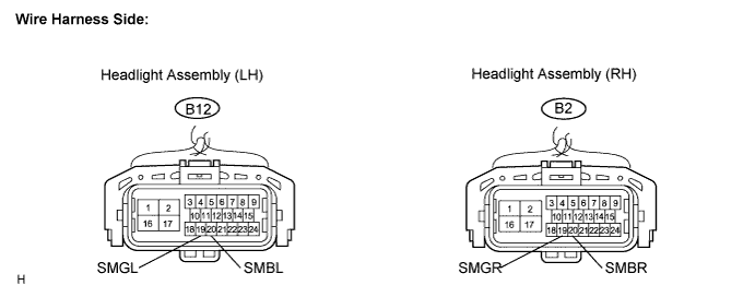
Disconnect the B12 and B2 headlight connectors.
Measure the voltage according to the value(s) in the table below.
- Standard voltage:
- LH Side (B2412):
Tester Connection
Condition
Specified Condition
B12-20 (SMBL) - B12-19 (SMGL)
Engine switch off
Below 1 V
Engine switch on (IG)
4.5 to 5.5 V
- RH Side (B2413):
Tester Connection
Condition
Specified Condition
B2-20 (SMBR) - B2-19 (SMGR)
Engine switch off
Below 1 V
Engine switch on (IG)
4.5 to 5.5 V
|
|
||||
| OK | |
|
| 5. REPLACE HEADLIGHT ASSEMBLY |
Temporarily replace the headlight assembly with a new or normally functioning one.
Check that headlight assembly operates.
- OK:
- Return to normal operation.
|
|
||||
| OK | ||
|
||
| ||