B1421/21
Diagnostic trouble codes
DESCRIPTION
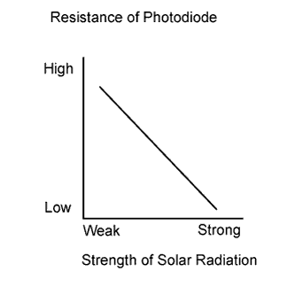

The solar sensor, which is installed on the upper side of the instrument panel, detects sunlight and controls the air conditioning in AUTO mode. The output voltage from the solar sensor varies according to the amount of sunlight. When the sunlight increases, the output voltage increases. As the sunlight decreases, the output voltage decreases. The A/C amplifier detects voltage output from the solar sensor.
| DTC No. |
DTC Detection Condition |
Trouble Area |
| B1421/21 |
Open or short in passenger side solar sensor circuit |
|
WIRING DIAGRAM
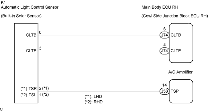
INSPECTION PROCEDURE
- HINT:
- If DTC B1244 is output at the same time, troubleshoot DTC B1244 first.
- If the check is performed in a dark place, DTC B1421/21 or B1424/24 (solar sensor circuit abnormal) may be output.
- If DTC B1244 is output at the same time, troubleshoot DTC B1244 first.
| 1. READ VALUE OF INTELLIGENT TESTER |

Connect the intelligent tester to the DLC3.
Turn the engine switch on (IG) and turn the intelligent tester main switch on.
Expose the sensing portion of the solar sensor to light.
- HINT:
- Use an incandescence light for inspection.
Select the item below in the Data List, and read the display on the intelligent tester.
| Item |
Measure Item / Display (Range) |
Normal Condition |
Diagnostic Note |
| Solar Sensor (P side) (Solar Sens-P) |
Passenger side solar sensor / Min.: 0, Max.: 255 |
Passenger side solar sensor value increases as brightness increases |
- |
- OK:
- The display is as specified in the normal condition column.
- Result:
Result
Proceed to
NG
A
OK (When troubleshooting according to the PROBLEM SYMPTOMS TABLE)
B
OK (When troubleshooting according to the DTC)
C
|
|
||||
|
|
||||

| A | |
 |
| 2. CHECK WIRE HARNESS (SOLAR SENSOR) |
Disconnect the solar sensor connector.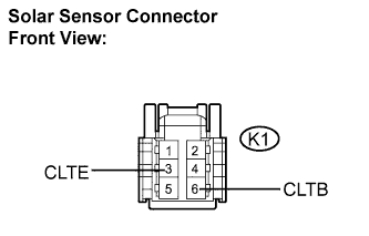
Measure the voltage according to the value(s) in the table below.
- Standard voltage:
Tester Connection
Condition
Specified Condition
K1-6 (CLTB) - K1-3 (CLTE)
Engine switch off
Below 1 V
K1-6 (CLTB) - K1-3 (CLTE)
Engine switch on (IG)
10 to 14 V
|
|
||||

| NG | |
|
| 3. CHECK WIRE HARNESS (MAIN BODY ECU RH - SOLAR SENSOR) |
Disconnect the main body ECU RH connector.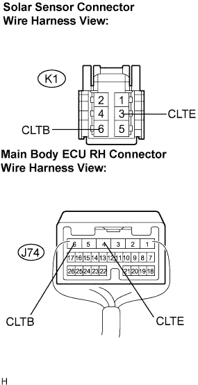
Measure the resistance according to the value(s) in the table below.
- Standard resistance:
Tester Connection
Condition
Specified Condition
J74-6 (CLTB) - K1-6 (CLTB)
Always
Below 1 Ω
J74-4 (CLTE) - K1-3 (CLTE)
Always
Below 1 Ω
J74-6 (CLTB) - Body ground
Always
10 kΩ or higher
J74-4 (CLTE) - Body ground
Always
10 kΩ or higher
|
|
||||
| OK | ||
 |
||
| ||
| 4. CHECK SOLAR SENSOR |
Remove the solar sensor with its connector still connected.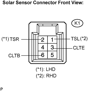
Apply battery voltage between terminals 6 (CLTB) and 3 (CLTE) of the solar sensor.
Measure the voltage according to the value(s) in the table below.
- Standard voltage:
- LHD:
Tester Connection
Condition
Specified Condition
K1-2 (TSR) - K1-3 (CLTE)
Sensor is subjected to electric light
0.8 to 4.3 V
K1-2 (TSR) - K1-3 (CLTE)
Sensor is covered with a cloth
Below 0.8 V
- Standard voltage:
- RHD:
Tester Connection
Condition
Specified Condition
K1-1 (TSL) - K1-3 (CLTE)
Sensor is subjected to electric light
0.8 to 4.3 V
K1-1 (TSL) - K1-3 (CLTE)
Sensor is covered with a cloth
Below 0.8 V
- NOTICE:
- The connection procedure for using a digital tester such as a TOYOTA electrical tester is shown above. When using an analog tester, connect the negative (-) lead to terminal 2 and positive (+) lead to terminal 1 of the solar sensor.
- While using the battery during inspection, do not bring the positive and negative tester probes too close to each other as a short circuit may occur.
- The connection procedure for using a digital tester such as a TOYOTA electrical tester is shown above. When using an analog tester, connect the negative (-) lead to terminal 2 and positive (+) lead to terminal 1 of the solar sensor.
- HINT:
- Use an incandescent light for inspection. Bring it within about 30 cm (11.8 in.) of the solar sensor.
- As the inspection light is moved away from the sensor, the voltage increases.
- Use an incandescent light for inspection. Bring it within about 30 cm (11.8 in.) of the solar sensor.
|
|
||||
| OK | |
|
| 5. CHECK WIRE HARNESS (SOLAR SENSOR - A/C AMPLIFIER) |
Disconnect the solar sensor connector.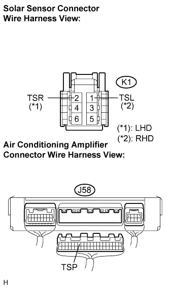
Disconnect the A/C amplifier connector.
Measure the resistance according to the value(s) in the table below.
- Standard resistance:
- LHD:
Tester Connection
Condition
Specified Condition
J58-14 (TSP) -K1-2 (TSR)
Always
Below 1 Ω
J58-14 (TSP) - Body ground
Always
10 kΩ or higher
- Standard resistance:
- RHD:
Tester Connection
Condition
Specified Condition
J58-14 (TSP) -K1-1 (TSL)
Always
Below 1 Ω
J58-14 (TSP) - Body ground
Always
10 kΩ or higher
|
|
||||
| OK | ||
|
||
| ||