B1422/22
Diagnostic trouble codes
DESCRIPTION
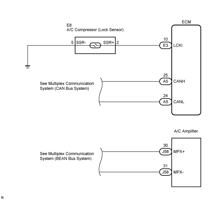
This sensor sends 1 pulse per engine revolution to the ECM.If the ratio between engine and compressor speed deviates 20% or more compared to normal operation, the ECM turns the cooler compressor off and the indicator blinks at approximately 1 second intervals.
The ECM informs the A/C amplifier of the operation condition of the cooler compressor through multiplex communication (CAN and BEAN).
| DTC No. |
DTC Detection Condition |
Trouble Area |
| B1422/22 |
Open or short in compressor lock sensor circuit |
|
WIRING DIAGRAM

INSPECTION PROCEDURE
| 1. CHECK MULTIPLEX COMMUNICATION SYSTEM |

Use the intelligent tester to check if the Multiplex Communication System (MPX) is functioning normally.
- Result:
Result
Proceed to
MPX DTC is not output
A
MPX DTC is output
B
|
|
||||

| A | |
 |
| 2. CHECK CAN COMMUNICATION SYSTEM |
Use the intelligent tester to check if the CAN Communication System is functioning normally.
- Result:
Result
Proceed to
CAN DTC is not output
A
CAN DTC is output
B
|
|
||||
| A | |
|
| 3. INSPECT ECM |
Remove the ECM with its connectors still connected.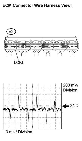
Measure the waveform of the connector.
- Standard:
Tester Connection
Condition
Specified Condition
E3-10 (LCKI) - Body ground
Engine switch on (IG)
AUTO switch ON
A/C switch ON
Magnetic clutch ON
Pulse generation
| Item |
Contents |
| Tool setting |
200 mV/DIV., 10 ms/DIV. |
| Vehicle condition |
Engine switch on (IG) AUTO switch ON A/C switch ON Magnetic clutch ON |
- Result:
Result
Proceed to
NG
A
OK (When troubleshooting according to the PROBLEM SYMPTOMS TABLE)
B
OK (When troubleshooting according to the DTC)
C
|
|
||||
|
|
||||
| A | |
|
| 4. INSPECT A/C COMPRESSOR (LOCK SENSOR) |
Disconnect the A/C compressor connector.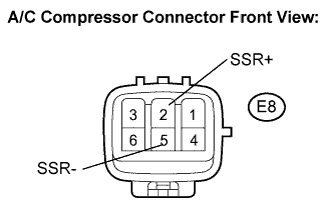
Measure the resistance according to the value(s) in the table below.
- Standard resistance:
Tester Connection
Specified Condition
E8-2 (SSR+) - E8-5 (SSR-)
160 to 320 Ω
|
|
||||
| OK | |
|
| 5. CHECK WIRE HARNESS (ECM - A/C COMPRESSOR) |
Disconnect the A/C compressor connector.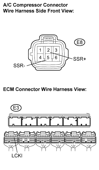
Disconnect the ECM connector.
Measure the resistance according to the value(s) in the table below.
- Standard resistance:
Tester Connection
Condition
Specified Condition
E3-10 (LCKI) - E8-2 (SSR+)
Always
Below 1 Ω
E3-10 (LCKI) - Body ground
Always
10 kΩ or higher
E8-5 (SSR-) - Body ground
Always
Below 1 Ω
|
|
||||
| OK | ||
 |
||
| ||