B1423/23
Diagnostic trouble codes
DESCRIPTION
This DTC is output when refrigerant pressure is extremely low (0.19 MPa (2.0 kgf/cm2, 28 psi) or less) or extremely high (3.14 MPa (32.0 kgf/cm2, 455 psi) or more). The pressure sensor, which is installed on the pipe of the high pressure side to detect refrigerant pressure, outputs a refrigerant pressure signal to the A/C amplifier. The A/C amplifier converts this signal to pressure according to the sensor characteristics to control the compressor.- HINT:
- Be sure to check the refrigerant volume first when this DTC is output because this DTC can also be output if there is no refrigerant in the system.
| DTC No. |
DTC Detection Condition |
Trouble Area |
| B1423/23 |
Open or short in pressure switch circuit |
|
WIRING DIAGRAM
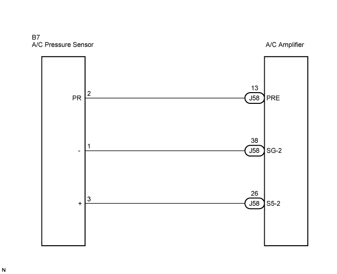

INSPECTION PROCEDURE
| 1. CHECK REFRIGERANT |

Check the sight glass of the cooler unit refrigerant liquid pipe.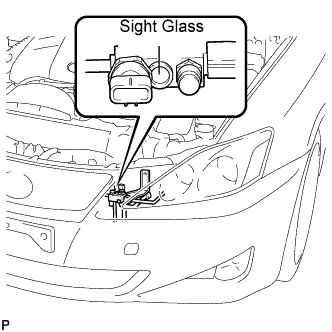
Prepare the vehicle according to the chart below.
Item
Condition
Vehicle Doors
Fully open
Temperature Setting
MAX COLD
Blower Speed
HI
A/C
ON
Compare the sight glass to the following chart.
| Item |
Symptom |
Amount of Refrigerant |
Corrective Actions |
| 1 |
Bubbles visible |
Insufficient* |
|
| 2 |
No bubbles visible |
Empty, insufficient, or excessive |
Refer to 3 and 4 |
| 3 |
No temperature difference between compressor inlet and outlet |
Empty or nearly empty |
|
| 4 |
Considerable temperature difference between compressor inlet and outlet |
Proper or excessive |
Refer to 5 and 6 |
| 5 |
Immediately after air conditioning is turned OFF, refrigerant clears |
Excessive |
|
| 6 |
Immediately after air conditioning is turned OFF, refrigerant foams and then becomes clear |
Proper |
- |
|
|
||||

| OK | |
 |
| 2. CHECK WIRE HARNESS (PRESSURE SENSOR - A/C AMPLIFIER) |
Disconnect the pressure sensor connector.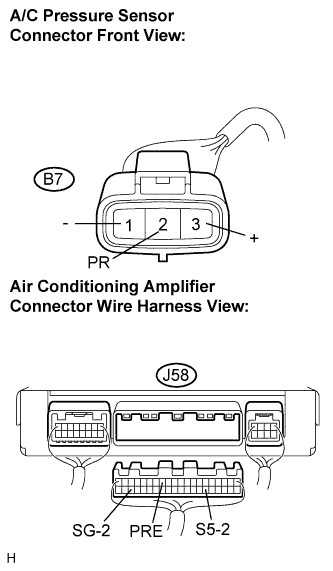
Disconnect the A/C amplifier connector.
Measure the resistance according to the value(s) in the table below.
- Standard resistance:
Tester Connection
Condition
Specified Condition
B7-2 (PR) - J58-13 (PRE)
Always
Below 1 Ω
B7-3 (+) - J58-26 (S5-2)
Always
Below 1 Ω
B7-1 (-) - J58-38 (SG-2)
Always
Below 1 Ω
J58-13 (PRE) - Body ground
Always
10 kΩ or higher
J58-26 (S5-2) - Body ground
Always
10 kΩ or higher
J58-38 (SG-2) - Body ground
Always
10 kΩ or higher
|
|
||||
| OK | |
|
| 3. INSPECT PRESSURE SENSOR |
Install the manifold gauge set (Click here).
Connect the three 1.5 V dry cell batterie's positive (+) lead to terminal 3 and the negative (-) lead to terminal 1. Then connect the voltmeter's positive (+) lead to terminal 2 and the negative (-) lead to terminal 1. Measure the voltage.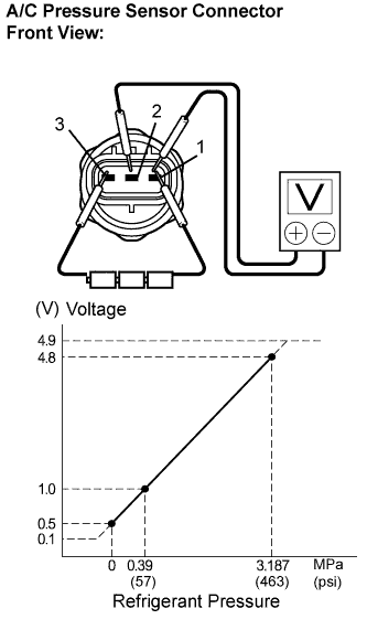
- OK:
- The voltage changes according to refrigerant pressure, as shown in the graph.
- Result:
Result
Proceed to
NG
A
OK (When troubleshooting according to the DTC)
B
OK (When troubleshooting according to the PROBLEM SYMPTOMS TABLE)
C
|
|
||||
|
|
||||
| A | ||
 |
||
| ||