P0230
Diagnostic trouble codes
DESCRIPTION
When the engine is cranked, a signal is sent from the ignition control ECU's STSW terminal to the ECM's STSW terminal. Then voltage travels from the ECM's STAR terminal through the park/neutral position switch to the STARTER relay coil. The STAR terminal also sends a signal to the STA terminal. When the STA signal and NE signal are input to the ECM, the ECM interior's Tr1 turns on, which causes power to be supplied to the C/OPN relay coil (C/OPN on). As a result, the F/PMP relay actuates, which causes the fuel pump to operate. If the engine is operating and NE signals are being output, the ECM interior's Tr1 is on (C/OPN on), and the fuel pump will continue operating. The fuel pump's has a high and low speed setting. When the engine is starting or operating with a heavy load, the ECM interior's Tr2 turns on to actuate the F/PMP relay so that the fuel pump operates at the high speed setting. When the engine is idling or operating with a light load, the Tr2 turns off, and current flows through the fuel pump resister to the fuel pump so that the fuel pump operates at the low speed setting.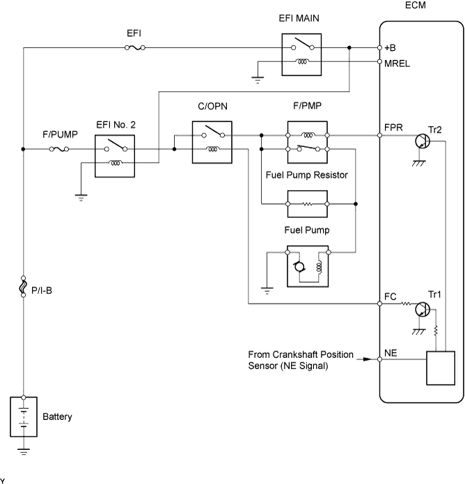

| DTC No. |
DTC Detection Condition |
Trouble Area |
| P0230 |
Open or short in F/PMP relay circuit (1 trip detection logic) |
|
WIRING DIAGRAM
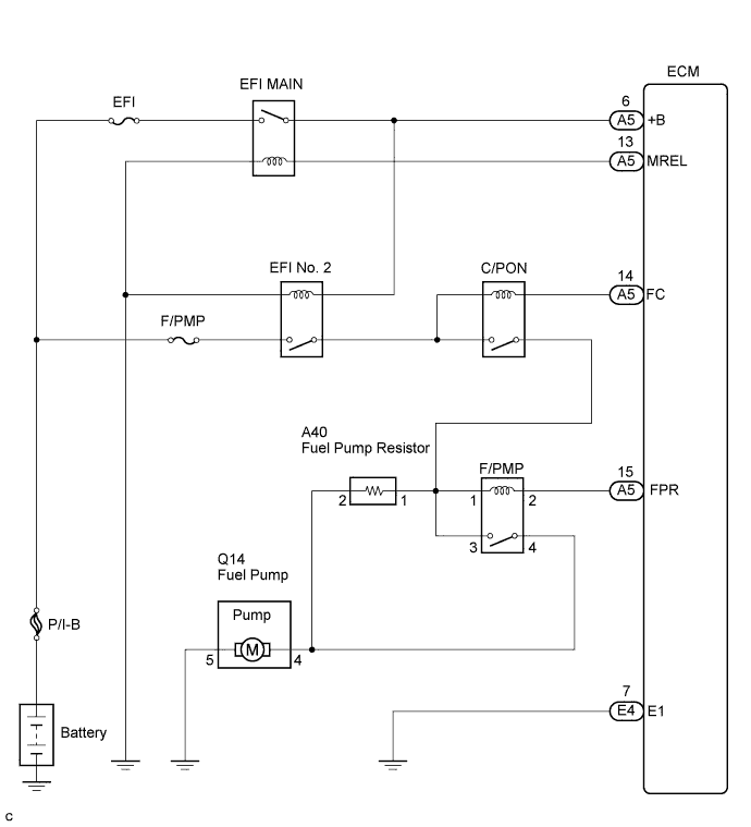
This troubleshooting procedure is based on the premise that the engine is started. If the engine is not started, proceed to the problem symptoms table (Click here).
INSPECTION PROCEDURE
| 1. CHECK ECM (FRP VOLTAGE) |

Measure the voltage of the ECM connectors.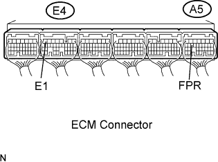
- Standard voltage:
Tester Connection
Condition
Specified Condition
FPR (A5- 15) - E1 (E4-7)
STA signal ON
9 to 14 V
FPR (A5-15) - E1 (E4-7)
STA signal OFF
0 to 3 V
|
|
||||

| OK | |
 |
| 2. INSPECT RELAY (Marking: F/PMP) |
Remove the F/PMP relay from the engine room J/B and R/B No. 2.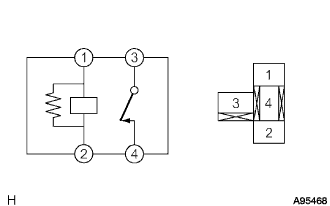
Measure the resistance of the F/PMP relay.
- Standard resistance:
Tester Connection
Specified Condition
3 - 4
Below 1 Ω
3 - 4
10 kΩ or more
(when battery voltage is applied to terminals 1 and 2)
|
|
||||
| OK | |
|
| 3. CHECK HARNESS AND CONNECTOR (F/PMP RELAY - ECM) |
Remove the F/PMP relay from the engine room J/B and R/B No. 2.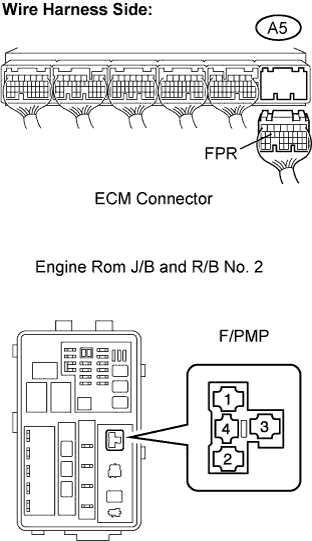
Disconnect the A5 ECM connector.
Measure the resistance of the wire harness side connector.
- Standard resistance:
Tester Connection
Specified Condition
F/PMP relay terminal 2 - A5-15 (FPR)
Below 1 Ω
F/PMP relay terminal 2 or A5-15 (FPR) - Body Ground
10 kΩ or higher
|
|
||||
| OK | ||
 |
||
| ||