P0200
Diagnostic trouble codes
DESCRIPTION
The high speed activation of the high pressure fuel injector is possible through the high-voltage, rapid-recharge DC/DC converter. Using high pressure fuel, the atomized fuel's injection timing can be accurately controlled, which decreases emissions and fuel consumption. The steady ECM checks the injector driver movement. When the injector driver or inject has a malfunction, the injection control of the relevant cylinder is stopped or power to the injector relay is cut. Then the ECM illuminates the check engine warning light.| DTC No. |
DTC Detection Condition |
Trouble Area |
| P0200 |
|
|
| P0201 P0202 P0203 P0204 P0205 P0206 P12FF |
NO INJF signals of each cylinder to ECM 20 times successively (1 trip detection logic) |
|
WIRING DIAGRAM
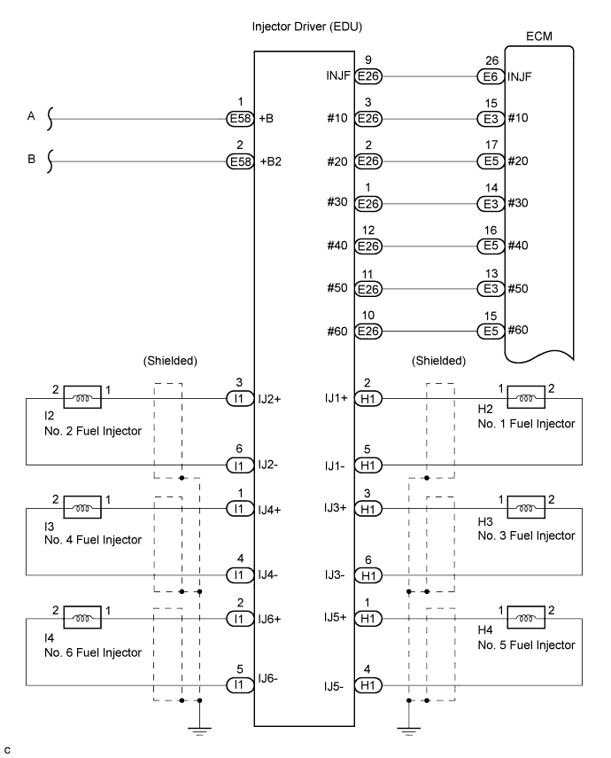

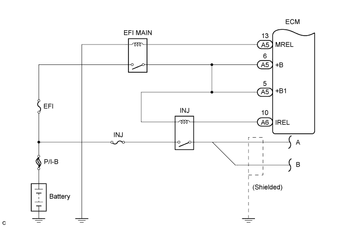
INSPECTION PROCEDURE
- HINT:
- Read freeze frame data using the intelligent tester. Freeze frame data records the engine conditions when malfunctions are detected. When troubleshooting, freeze frame data can help determine if the vehicle was moving or stationary, if the engine was warmed up or not, if the air-fuel ratio was lean or rich, and other data from the time the malfunction occurred (Click here).
| 1. INSPECT INJECTOR DRIVER (POWER SOURCE OF EDU) |

Disconnect the E58 injector driver (EDU) connector.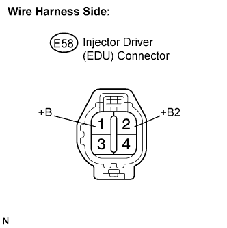
Turn the engine switch on (IG).
Measure the voltage of the injector driver (EDU) connector.
- Standard voltage:
Tester Connection
Specified Condition
+B (E58-1) - Engine ground
10 to 14 V
+B2 (E58-2) - Engine ground
10 to 14 V
Reconnect the injector driver (EDU) connector.
|
|
||||

| OK | |
 |
| 2. CHECK HARNESS AND CONNECTOR (EDU - FUEL INJECTOR) |
Disconnect the N1 and I1 connectors.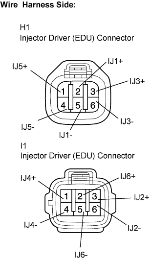
Measure the resistance of the injector driver (EDU) connector.
- Standard resistance:
Tester Connection
Condition
Specified Condition
IJ1+ (H1-2) - IJ1- (H1-5)
20°C (68°F)
2.01 to 2.31 Ω
IJ2+ (I1-3) - IJ2- (I1-6)
20°C (68°F)
2.01 to 2.31 Ω
IJ3+ (H1-3) - IJ3- (H1-6)
20°C (68°F)
2.01 to 2.31 Ω
IJ4+ (I1-1) - IJ4- (I1-4)
20°C (68°F)
2.01 to 2.31 Ω
IJ5+ (H1-1) - IJ5- (H1-4)
20°C (68°F)
2.01 to 2.31 Ω
IJ6+ (I1-2) - IJ6- (I1-5)
20°C (68°F)
2.01 to 2.31 Ω
Reconnect the injector driver (EDU) connector.
|
|
||||

| OK | |
|
| 3. CHECK HARNESS AND CONNECTOR (ECM - EDU) |
Disconnect the E3, E5 and E6 connectors.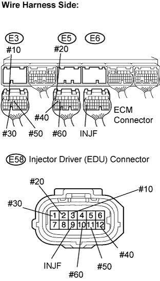
Disconnect the E58 injector driver (EDU) connector.
Measure the resistance of the wire harness side connectors.
- Standard resistance (Check for open):
Tester Connection
Specified Condition
#10 (E3-15) - #10 (E58-3)
Below 1 Ω
#20 (E5-17) - #20 (E58-2)
Below 1 Ω
#30 (E3-14) - #30 (E58-1)
Below 1 Ω
#40 (E5-16) - #40 (E58-12)
Below 1 Ω
#50 (E3-13) - #50 (E58-11)
Below 1 Ω
#60 (E5-15) - #60 (E58-10)
Below 1 Ω
INJF (E6-26) - INJF (E58-9)
Below 1 Ω
- Standard resistance (Check for short):
Tester Connection
Specified Condition
#10 (E3-15) or #10 (E58-3) - Engine ground
10 kΩ or higher
#20 (E5-17) or #20 (E58-2) - Engine ground
10 kΩ or higher
#30 (E3-14) or #30 (E58-1) - Engine ground
10 kΩ or higher
#40 (E5-16) or #40 (E58-12) - Engine ground
10 kΩ or higher
#50 (E3-13) or #50 (E58-11) - Engine ground
10 kΩ or higher
#60 (E5-15) or #60 (E58-10) - Engine ground
10 kΩ or higher
INJF (E6-26) or INJF (E58-9) - Engine ground
10 kΩ or higher
Reconnect the ECM connector.
Reconnect the injector driver (EDU) connector.
|
|
||||
| OK | |
|
| 4. CHECK ECM (#10, #20, #30, #40, #50 AND #60 VOLTAGE) |
Connect an oscilloscope to terminals #10 to #60 and E1 of the E3, E4 and E5 ECM harness side connectors.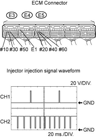
With the engine cranking or idling, check the signal waveform.
- Standard:
- Signal waveform appears as shown in the illustration.
ECM Terminal Name
CH1: #10 (E3-15) - E1 (E4-7)
CH1: #20 (E5-17) - E1 (E4-7)
CH1: #30 (E3-14) - E1 (E4-7)
CH1: #40 (E5-16) - E1 (E4-7)
CH1: #50 (E3-13) - E1 (E4-7)
CH1: #60 (E5-15) - E1 (E4-7)
Tester Range
20 V/DIV., 20 ms./DIV.
Condition
Idling after warming up engine
- HINT:
- Check the waveform before the ECM detects the DTC(s) and enters the fail-safe mode, because the ECM will no more indicate the output voltage once it enters the fail-safe mode.
|
|
||||
| OK | |
|
| 5. CHECK ECM (INJF VOLTAGE) |
Connect an oscilloscope to terminals INJF and E1 of the E6 and E7 ECM harness side connectors.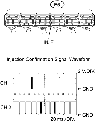
With the engine cranking or idling, check the signal waveform.
- Standard voltage:
- Signal waveform appears as shown in the illustration.
ECM Terminal Name
CH2: INJF (E6-26) - E1 (E4-7)
Tester Range
20 V/DIV., 20 ms./DIV.
Condition
Idling after warming up engine
- HINT:
- Check the waveform before the ECM detects the DTC(s) and enters the fail-safe mode, because the injector driver (EDU) will no more indicate the output voltage once it enters the fail-safe mode.
|
|
||||
| OK | ||
 |
||
| ||
| 6. INSPECT FUEL INJECTOR (RESISTANCE) |
Check the resistance of the fuel injector (Click here).
|
|
||||
| OK | ||
|
||
| ||