Blower Motor Circuit
Circuit diagnosis
DESCRIPTION
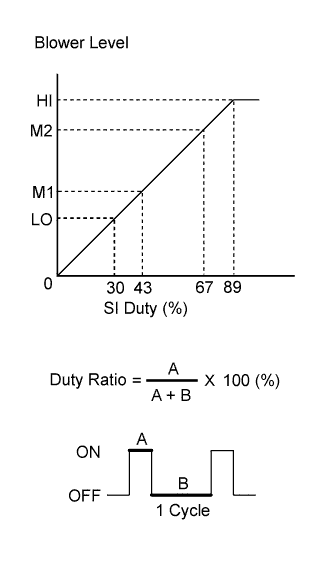

The blower motor is operated by signals from the A/C amplifier. The blower motor speed is controlled using various duty ratios.
- The duty ratio is the ratio of the blower motor ON time (A) to the total of the blower motor ON and OFF time (A + B).
- The blower motor controller controls the blower motor speed.
WIRING DIAGRAM
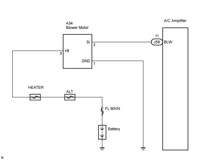
INSPECTION PROCEDURE
| 1. PERFORM ACTIVE TEST BY INTELLIGENT TESTER |

Connect the intelligent tester to the DLC3.
Turn the engine switch on (IG) and turn the intelligent tester main switch on.
Select the item below in the Active Test and then check that the relay operates.
| Item |
Test Details / Display (Range) |
Diagnostic Note |
| Blower Motor (Blower Motor) |
Blower motor / Min.: Level 01, Max.: Level 31 |
- |
- Result:
Result
Proceed to
OK
A
NG (blower motor does not operate)
B
NG (blower motor operates but does not change speed)
C
|
|
||||
|
|
||||

| A | ||
 |
||
| ||
| 2. INSPECT FUSE |
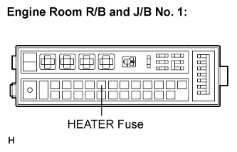 |
Remove the HEATER fuse from the engine room R/B and J/B No. 1.
Measure the resistance according to the value(s) in the table below.
- Standard resistance:
Tester Item
Condition
Specified Condition
HEATER fuse
Always
Below 1 Ω
|
|
||||

| OK | |
 |
| 3. CHECK WIRE HARNESS (BLOWER MOTOR - BODY GROUND) |
Disconnect the blower motor connector.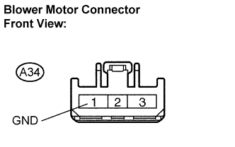
Measure the resistance according to the value(s) in the table below.
- Standard resistance:
Tester Connection
Condition
Specified Condition
A34-1 (GND) - Body ground
Always
Below 1 Ω
|
|
||||
| OK | |
|
| 4. CHECK WIRE HARNESS (BLOWER MOTOR - BATTERY) |
Disconnect the blower motor connector.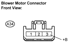
Measure the voltage according to the value(s) in the table below.
- Standard voltage:
Tester Connection
Condition
Specified Condition
A34-3 (+B) - Body ground
Always
10 to 14 V
|
|
||||
| OK | |
|
| 5. INSPECT BLOWER MOTOR |
Disconnect the A/C amplifier connector.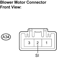
Connect the blower motor connector.
Measure the voltage according to the value(s) in the table below.
- Standard voltage:
Tester Connection
Condition
Specified Condition
A34-2 (SI) - Body ground
Engine switch on (IG)
4.5 to 5.5 V
|
|
||||
| OK | |
|
| 6. CHECK WIRE HARNESS (A/C AMPLIFIER - BODY GROUND) |
Disconnect the A/C amplifier connector.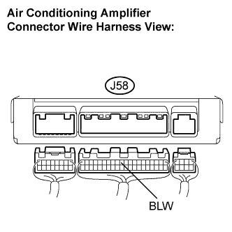
Measure the voltage according to the value(s) in the table below.
- Standard voltage:
Tester Connection
Condition
Specified Condition
J58-11 (BLW) - Body ground
Engine switch on (IG)
4.5 to 5.5 V
|
|
||||
| OK | |
|
| 7. INSPECT AIR CONDITIONING AMPLIFIER |
Remove the A/C amplifier with its connectors still connected.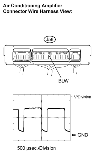
Turn the engine switch on (IG) .
Turn the blower switch ON (Lo).
Measure the waveform between terminal J58-11 (BLW) of the A/C amplifier and body ground.
- OK:
- Waveform is as shown in the illustration.
- HINT:
- Waveform varies with the blower level.
| Item |
Contents |
| Tool setting |
1 V/DIV., 500 μs/DIV. |
| Vehicle condition |
Engine switch on (IG) Blower switch ON (Lo) |
|
|
||||
| OK | ||
|
||
| ||