Air Conditioning Compressor Magnetic Clutch Circuit
Circuit diagnosis
DESCRIPTION
The A/C amplifier sends a magnetic clutch ON command signal to the ECM through the BEAN line and CAN line. Then the ECM turns the A/C COMP relay on to turn the magnetic clutch on.WIRING DIAGRAM
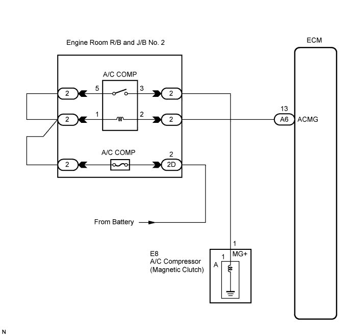

INSPECTION PROCEDURE
| 1. CHECK MULTIPLEX COMMUNICATION SYSTEM |

Use the intelligent tester to check if the Multiplex Communication System (MPX) is functioning normally.
- Result:
Result
Proceed to
MPX DTC is not output
A
MPX DTC is output
B
|
|
||||

| A | |
 |
| 2. CHECK CAN COMMUNICATION SYSTEM |
Use the intelligent tester to check if the CAN Communication System is functioning normally.
- Result:
Result
Proceed to
CAN DTC is not output
A
CAN DTC is output
B
|
|
||||
| A | |
|
| 3. READ VALUE OF INTELLIGENT TESTER |
Connect the intelligent tester to the DLC3.
Turn the engine switch on (IG) and turn the intelligent tester main switch on.
Turn the A/C switch on and off.
Select the item below in the Data List, and read the display on the intelligent tester.
Data List / Engine: Item
Measure Item
Normal Condition
Diagnostic Note
A/C Signal
(A/C Signal)
A/C signal / ON or OFF
ON: A/C ON
OFF: A/C OFF
-
- OK:
- The display is as specified in the normal condition column.
|
|
||||

| OK | |
|
| 4. READ VALUE OF INTELLIGENT TESTER |
Connect the intelligent tester to the DLC3.
Turn the engine switch on (IG) and turn the intelligent tester main switch on.
Change the blower fan speed to LO using the blower switch.
Turn the A/C switch on and off.
Select the item below in the Data List, and read the display on the intelligent tester.
Data List / Engine: Item
Measure Item
Normal Condition
Diagnostic Note
A/C Magnetic Clutch Relay
(A/C Magnetic Clutch Relay)
A/C magnetic clutch relay / OFF, ON
ON: A/C magnetic clutch ON
OFF: A/C magnetic clutch OFF
-
- OK:
- The display is as specified in the normal condition.
|
|
||||
| OK | |
|
| 5. PERFORM ACTIVE TEST BY INTELLIGENT TESTER |
Connect the intelligent tester to the DLC3.
Turn the engine switch on (IG) and turn the intelligent tester main switch on.
Select the item below in the Active Test and read the display on the intelligent tester.
| Item |
Test Details / Display (Range) |
Diagnostic Note |
| Magnetic Clutch Relay (A/C Mag Clutch) |
Magnetic Clutch Relay / OFF, ON |
- |
- OK:
- The magnetic clutch operates normally.
|
|
||||
| NG | |
|
| 6. INSPECT FUSE (A/C COMP) |
Remove the A/C COMP fuse from the engine room R/B and J/B No. 2.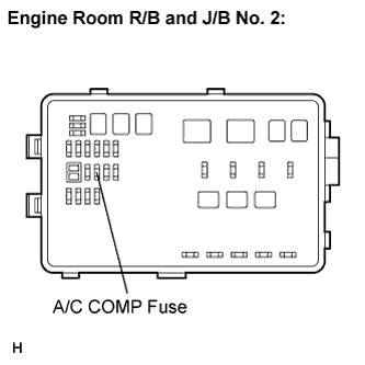
Measure the resistance of the fuse.
- Standard resistance:
Tester Item
Condition
Specified Condition
A/C COMP fuse
Always
Below 1 Ω
|
|
||||
| OK | |
|
| 7. INSPECT RELAY (A/C COMP) |
Remove the A/C COMP relay from the engine room R/B and J/B No. 2.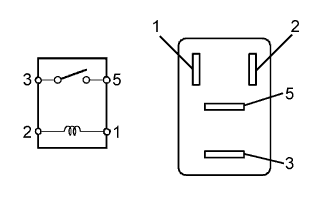
Measure the resistance according to the value(s) in the table below.
- Standard resistance:
Tester Connection
Specified Condition
3 - 5
10 kΩ or higher
3 - 5
Below 1 Ω
(when battery voltage is applied to terminals 1 and 2)
|
|
||||
| OK | |
|
| 8. INSPECT A/C COMPRESSOR |
Disconnect the A/C compressor connector.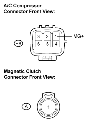
Disconnect the magnetic clutch connector.
Measure the resistance according to the value(s) in the table below.
- Standard resistance:
Tester Connection
Condition
Specified Condition
E8-1 (MG+) - A-1
Always
Below 1 Ω
E8-1 (MG+) - Body ground
Always
10 kΩ or higher
|
|
||||
| OK | |
|
| 9. INSPECT MAGNETIC CLUTCH |
Measure the resistance of the connector.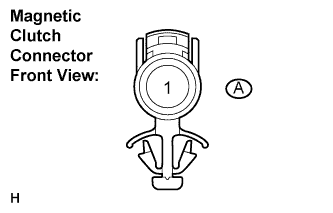
- Standard resistance:
Tester Connection
Condition
Specified Condition
A-1 - Body ground
Always
3.4 to 3.8 Ω
When connector terminal A1 is connected to the positive (+) battery terminal, check that the following occurs: 1) the magnetic clutch's operating sound can be heard, and 2) the magnetic clutch's hub and rotor lock.
|
|
||||
| OK | |
|
| 10. CHECK WIRE HARNESS (ENGINE ROOM R/B AND J/B NO. 2 - A/C COMPRESSOR) |
Turn the engine switch on (IG).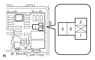
Measure the voltage according to the value(s) in the table below.
- Standard voltage:
Tester Connection
Specified Condition
Relay block A/C COMP relay terminal 5 - Body ground
10 to 14 V
Relay block A/C COMP relay terminal 1 - Body ground
10 to 14 V
|
|
||||
| OK | |
|
| 11. CHECK WIRE HARNESS (ENGINE ROOM R/B AND J/B NO. 2 - ECM) |
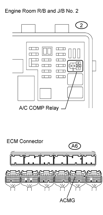 |
Disconnect the ECM connector.
Measure the resistance according to the value(s) in the table below.
- Standard resistance:
Tester Connection
Specified Condition
Relay block A/C COMP relay terminal 2 - A6-13 (ACMG)
Below 1 Ω
A6-13 (ACMG) - Body ground
10 kΩ or higher
|
|
||||
| OK | ||
 |
||
| ||
| 12. REPLACE AIR CONDITIONING AMPLIFIER |
Replace the A/C amplifier with a normal one and check that the condition returns to normal.
- OK:
- Same problem does not occur.
|
|
||||
| NG | ||
|
||
| ||