Door Courtesy Switch Circuit
Circuit diagnosis
DESCRIPTION
The main body ECU RH detects the condition of each door courtesy switch and sends a signal to each ECU via the multiplex communication circuit.WIRING DIAGRAM
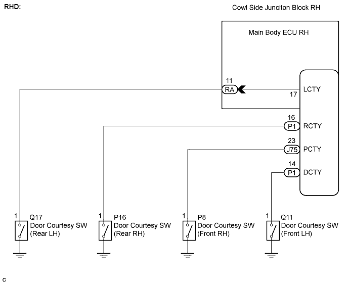

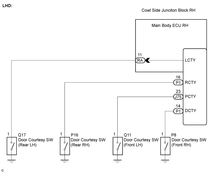
INSPECTION PROCEDURE
- HINT:
- The procedure is the same for each door courtesy switch circuit. First, inspect the suspected door courtesy switch circuit.
| 1. READ VALUE OF INTELLIGENT TESTER |

Connect the intelligent tester to the DLC3.
Turn the engine switch on (IG).
Turn the intelligent tester main switch on.
Select the item below in the DATA LIST for proper functioning of the courtesy switch.
DATA LIST: Main Body (Main Body ECU LH) Item
Measurement Item / Display
(Range)
Normal Condition
Diagnostic Note
D Door Courtesy Switch
Driver side door courtesy switch / ON or OFF
ON: Driver side door is open
OFF: Driver side door is closed
-
P Door Courtesy Switch
Passenger side door courtesy switch / ON or OFF
ON: Passenger side door is open
OFF: Passenger side door is closed
-
Rear Door Courtesy Switch
Rear (LH and RH) door courtesy switch / ON or OFF
ON: Rear door (LH or RH) is open
OFF: Rear door (LH and RH) is closed
-
- OK:
- Condition sign can be displayed.
- Result:
Result
Proceed to
OK
A
Driver side door courtesy switch does not operate
B
Front passenger side door courtesy switch does not operate
C
Both rear door courtesy switches do not operate
D
|
|
||||
|
|
||||
|
|
||||

| A | ||
 |
||
| ||
| 2. INSPECT DOOR COURTESY SWITCH (FRONT LH) |
- OK:
- Door courtesy switch is normal.
|
|
||||

| OK | |
 |
| 3. CHECK HARNESS AND CONNECTOR (DOOR COURTESY SWITCH (FRONT LH) - MAIN BODY ECU RH) |
Disconnect the P1 ECU connector.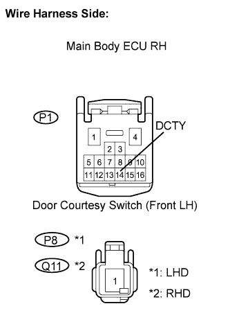
Disconnect the Q11 switch connector.
Measure the resistance of the wire harness side connectors.
- Standard resistance:
- LHD:
Tester Connection
Condition
Specified Condition
P1-14 (DCTY) - Q11-1
Always
Below 1 Ω
P1-14 (DCTY) or Q11-1 - Body ground
Always
10 kΩ or higher
- RHD:
Tester Connection
Condition
Specified Condition
P1-14 (DCTY) - P8-1
Always
Below 1 Ω
P1-14 (DCTY) or P8-1 - Body ground
Always
10 kΩ or higher
|
|
||||
| OK | ||
|
||
| ||
| 4. INSPECT DOOR COURTESY SWITCH (FRONT RH) |
- OK:
- Door courtesy switch is normal.
|
|
||||
| OK | |
|
| 5. CHECK HARNESS AND CONNECTOR (DOOR COURTESY SWITCH (FRONT RH) - MAIN BODY ECU RH) |
Disconnect the J75 ECU connector.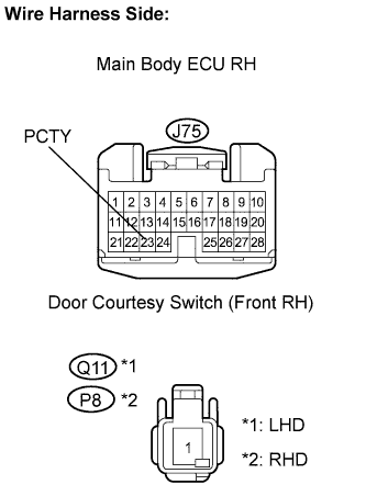
Disconnect the P8 switch connector.
Measure the resistance of the wire harness side connectors.
- Standard resistance:
- RHD:
Tester Connection
Condition
Specified Condition
J75-23 (PCTY) - P8-1
Always
Below 1 Ω
J75-23 (PCTY) or P8-1 - Body ground
Always
10 kΩ or higher
- LHD:
Tester Connection
Condition
Specified Condition
J75-23 (PCTY) - Q11-1
Always
Below 1 Ω
J75-23 (PCTY) or Q11-1 - Body ground
Always
10 kΩ or higher
|
|
||||
| OK | ||
|
||
| ||
| 6. INSPECT DOOR COURTESY SWITCH (REAR LH AND REAR RH) |
- OK:
- Door courtesy switch is normal.
|
|
||||
| OK | |
|
| 7. CHECK HARNESS AND CONNECTOR (DOOR COURTESY SWITCH (REAR LH OR REAR RH) - MAIN BODY ECU RH) |
Check the wire harness between the cowl side junction block RH and door courtesy switch (rear LH).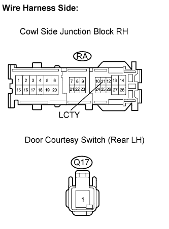
Disconnect the RA junction block connector.
Disconnect the Q17 switch connector.
Measure the resistance of the wire harness side connectors.
- Standard resistance:
Tester Connection
Condition
Specified Condition
RA-11 (LCTY) - Q17-1
Always
Below 1 Ω
RA-11(LCTY) or Q17-1 - Body ground
Always
10 kΩ or higher
Check the wire harness between the main body ECU RH and door courtesy switch (rear RH).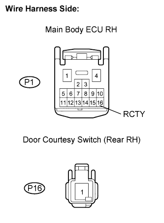
Disconnect the P1 ECU connector.
Disconnect the P16 switch connector.
Measure the resistance of the wire harness side connectors.
- Standard resistance:
Tester Connection
Condition
Specified Condition
P1-16 (RCTY) - P16-1
Always
Below 1 Ω
P1-16 (RCTY) or P16-1 - Body ground
Always
10 kΩ or higher
|
|
||||
| OK | ||
|
||
| ||