Headlight Signal Circuit
Circuit diagnosis
DESCRIPTION
The main body ECU RH receives the HEAD position signal from the combination switch as a backup link. It also receives the signal from the combination switch via the multiplex communication system.If this link is grounded, the headlights will illuminate.
WIRING DIAGRAM
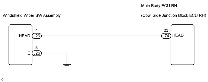

INSPECTION PROCEDURE
| 1. CHECK HARNESS AND CONNECTOR (MAIN BODY ECU RH - COMBINATION SWITCH ASSEMBLY) |

Disconnect the J26 combination switch connector.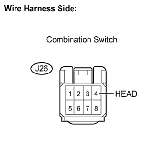
Measure the voltage according to the value(s) in the table below.
- Standard voltage:
Tester Connection
Condition
Specified Condition
J26-4 (HEAD) - Body ground
Always
10 to 14 V
|
|
||||

| OK | |
 |
| 2. CHECK HARNESS AND CONNECTOR (MAIN BODY ECU RH - COMBINATION SWITCH) |
Connect the J26 combination switch connector.
Measure the voltage according to the value(s) in the table below.
- Standard voltage:
Tester Connection
Condition
Specified Condition
J26-4 (HEAD) - Body ground
Light control switch position is off position
10 to 14 V
J26-4 (HEAD) - Body ground
Light control switch position is HEAD position
Below 1 V
|
|
||||
| OK | ||
 |
||
| ||
| 3. CHECK HARNESS AND CONNECTOR (COMBINATION SWITCH ASSEMBLY - BODY GROUND) |
Disconnect the J26 combination switch connector.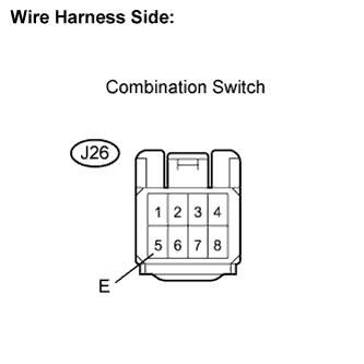
Measure the resistance according to the value(s) in the table below.
- Standard resistance:
Tester Connection
Condition
Specified Condition
J26-5 (E) - Body ground
Always
Below 1 Ω
|
|
||||

| OK | ||
|
||
| ||
| 4. CHECK HARNESS AND CONNECTOR (MAIN BODY ECU RH - COMBINATION SWITCH) |
Disconnect the J74 ECU connector.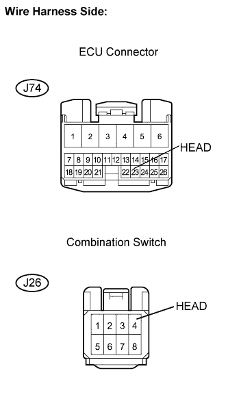
Disconnect the J26 combination switch connector.
Measure the resistance according to the value(s) in the table below.
- Standard resistance:
Tester Connection
Condition
Specified Condition
J74-23 (HEAD) - J26-4 (HEAD)
Always
Below 1 Ω
J74-23 (HEAD) - Body ground
Always
10 kΩ or higher
|
|
||||
| OK | ||
|
||
| ||