Taillight Circuit
Circuit diagnosis
DESCRIPTION
Front light:The front controller controls the operation of the FR TAIL relay. The FR TAIL relay turns on the front parking lights.
The front controller receives front parking light ON request signals from the combination switch ECU through BEAN communication and activates the FR TAIL relay.
The FR TAIL relay is built into the front controller, so unlike conventional relays, it cannot be removed for inspection.
Rear light:
The main body ECU RH controls the operation of the TAIL relay. The TAIL relay turns on the taillights and license plate lights.
The main body ECU RH receives taillight and license plate light ON request signals from the combination switch ECU through BEAN communication and activates the TAIL relay.
The TAIL relay is built into the cowl side J/B LH, so unlike conventional relays, it cannot be removed for inspection.
WIRING DIAGRAM
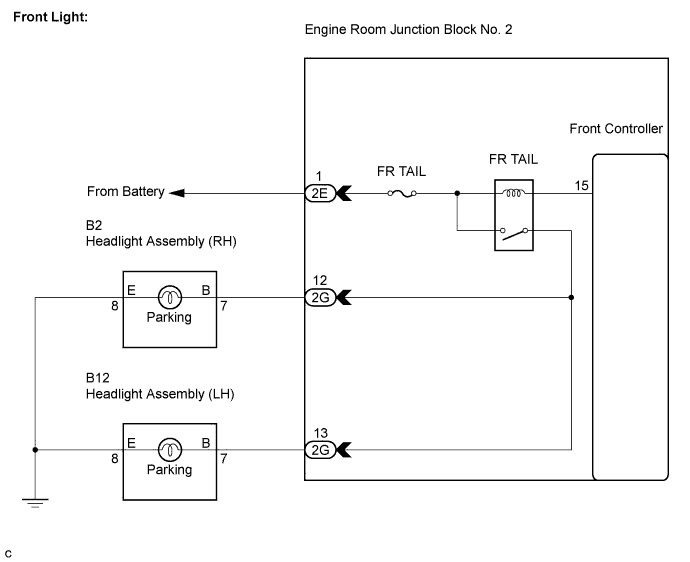

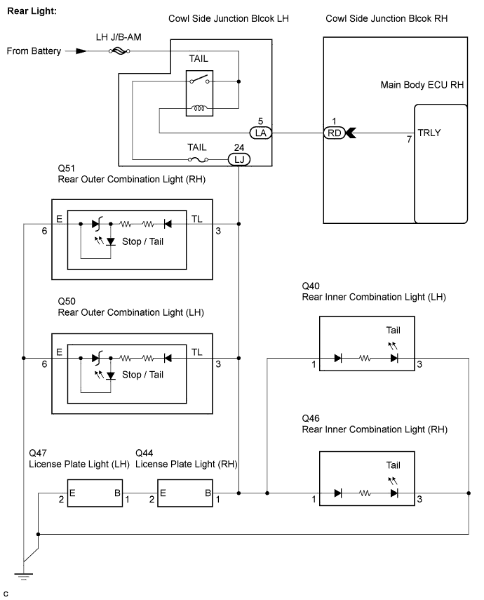
INSPECTION PROCEDURE
- NOTICE:
- Before proceeding to the following flowchart, check that the fuses are not blown and that the bulbs are not burned out.
| 1. CHECK TAILLIGHT (OPERATION) |

Turn the engine switch on (IG).
When the taillight switch is operated, check that the following lights illuminate.
- HINT:
- The front lights (parking lights) share the same drive circuit. Therefore, if one of the front lights does not come on, there may be a problem in the circuit between the FR TAIL relay and bulb, or the circuit between the bulb and body ground. Inspect those circuits to identify the problem.
- The rear lights (taillights and license plate lights) share the same drive circuit. Therefore, if one of the rear lights does not come on, there may be a problem in the circuit between the TAIL relay and the bulb or LED, or the circuit between the bulb or LED and body ground. Inspect those circuits to identify the problem.
- The front lights (parking lights) share the same drive circuit. Therefore, if one of the front lights does not come on, there may be a problem in the circuit between the FR TAIL relay and bulb, or the circuit between the bulb and body ground. Inspect those circuits to identify the problem.
- Result:
Result
Proceed to
Neither front nor rear lights illuminate
A
Front lights (parking lights) do not illuminate
B
Rear lights (taillights and license plate lights) do not illuminate
C
|
|
||||
|
|
||||

| A | ||
 |
||
| ||
| 2. PERFORM ACTIVE TEST BY INTELLIGENT TESTER |
Connect the intelligent tester to the DLC3.
Turn the engine switch on (IG).
Turn the intelligent tester on.
Select the item(s) in the ACTIVE TEST, and check the operation.
ACTIVE TEST: Body No. 5 (Front Controller) Item
Test Details
Diagnostic Note
Clearance Light Operation
Clearance light (Front parking lights) ON / OFF
-
- OK:
- Front parking lights illuminate.
|
|
||||
| OK | ||
|
||
| ||
| 3. CHECK HARNESS AND CONNECTOR (HEADLIGHT - BODY GROUND) |
- HINT:
- Perform the following inspection on either the LH or RH side.
Disconnect the B2 or B12 headlight connector.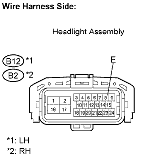
Measure the resistance according to the value(s) in the table below.
- Standard resistance:
- RH side:
Tester Connection
Condition
Specified Condition
B2-8 (E) - Body ground
Always
Below 1 Ω
- LH side:
Tester Connection
Condition
Specified Condition
B12-8 (E) - Body ground
Always
Below 1 Ω
|
|
||||

| OK | |
 |
| 4. CHECK HARNESS AND CONNECTOR (HEADLIGHT - BODY GROUND) |
- HINT:
- Perform the following inspection on either the LH or RH side.
Disconnect the B2 or B12 headlight connector.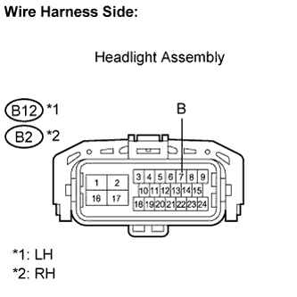
Measure the voltage according to the value(s) in the table below.
- Standard voltage:
- RH side:
Tester Connection
Condition
Specified Condition
B2-7 (B) - Body ground
Engine switch off
Below 1 V
B2-7 (B) - Body ground
Engine switch on (IG) and taillights on
10 to 14 V
- LH side:
Tester Connection
Condition
Specified Condition
B12-7 (B) - Body ground
Engine switch off
Below 1 V
B12-7 (B) - Body ground
Engine switch on (IG) and taillights on
10 to 14 V
|
|
||||
| OK | ||
|
||
| ||
| 5. CHECK HARNESS AND CONNECTOR (HEADLIGHT - ENGINE ROOM NO. 2 R/B) |
- HINT:
- Perform the following inspection on either the LH or RH side.
Disconnect the B2 or B12 headlight connector.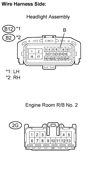
Disconnect the 2G engine room R/B No. 2 connector.
Measure the resistance according to the value(s) in the table below.
- Standard resistance:
- RH side:
Tester Connection
Condition
Specified Condition
B2-7 (B) - 2G-8
Always
Below 1 Ω
B2-7 (B) - Body ground
Always
10 kΩ or higher
- LH side:
Tester Connection
Condition
Specified Condition
B12-7 (B) - 2G-9
Always
Below 1 Ω
B12-7 (B) - Body ground
Always
10 kΩ or higher
|
|
||||
| OK | ||
|
||
| ||
| 6. PERFORM ACTIVE TEST BY INTELLIGENT TESTER |
Connect the intelligent tester to the DLC3.
Turn the engine switch on (IG).
Turn the intelligent tester on.
Select the item(s) in the ACTIVE TEST, and check the operation.
ACTIVE TEST: Main Body (Main Body ECU RH) Item
Test Details
Diagnostic Note
Tail Light
Taillights (taillights, license plate lights and side marker lights) ON / OFF
-
- OK:
- Taillights and license plate lights illuminate.
- Result:
Result
Proceed to
Inner taillights do not illuminate
A
Outer taillights do not illuminate
B
License plate lights do not illuminate
C
All rear lights illuminate
D
All rear lights do not illuminate
E
|
|
||||
|
|
||||
|
|
||||
|
|
||||
| A | |
|
| 7. CHECK HARNESS AND CONNECTOR (INNER TAILLIGHT - BODY GROUND) |
- HINT:
- Perform the following inspection on either the LH or RH side.
Disconnect the Q46 or Q40 inner taillight connector.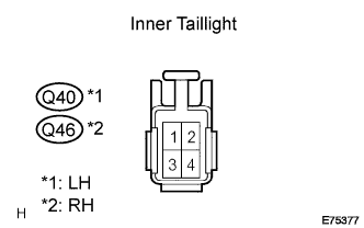
Measure the resistance according to the value(s) in the table below.
- Standard resistance:
- RH side:
Tester Connection
Condition
Specified Condition
Q46-3 - Body ground
Always
Below 1 Ω
- LH side:
Tester Connection
Condition
Specified Condition
Q40-3 - Body ground
Always
Below 1 Ω
|
|
||||
| OK | |
|
| 8. CHECK HARNESS AND CONNECTOR (INNER TAILLIGHT - MAIN BODY ECU LH) |
- HINT:
- Perform the following inspection on either the LH or RH side.
Disconnect the Q46 or Q40 inner taillight connector.
Measure the voltage according to the value(s) in the table below.
- Standard voltage:
- RH side:
Tester Connection
Condition
Specified Condition
Q46-1 - Body ground
Engine switch off
Below 1 V
Q46-1 - Body ground
Engine switch on (IG) and taillights on
10 to 14 V
- LH side:
Tester Connection
Condition
Specified Condition
Q40-1 - Body ground
Engine switch off
Below 1 V
Q40-1 - Body ground
Engine switch on (IG) and taillights on
10 to 14 V
|
|
||||
| OK | ||
|
||
| ||
| 9. CHECK HARNESS AND CONNECTOR (OUTER TAILLIGHT - BODY GROUND) |
- HINT:
- Perform the following inspection on either the LH or RH side.
Disconnect the Q51 or Q50 outer taillight connector.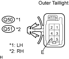
Measure the resistance according to the value(s) in the table below.
- Standard resistance:
- RH side:
Tester Connection
Condition
Specified Condition
Q51-6 (E) - Body ground
Always
Below 1 Ω
- LH side:
Tester Connection
Condition
Specified Condition
Q50-6 (E) - Body ground
Always
Below 1 Ω
|
|
||||
| OK | |
|
| 10. CHECK HARNESS AND CONNECTOR (OUTER TAILLIGHT - MAIN BODY ECU LH) |
- HINT:
- Perform the following inspection on either the LH or RH side.
Disconnect the Q51 or Q50 outer taillight connector.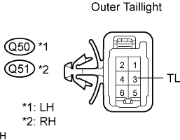
Measure the voltage according to the value(s) in the table below.
- Standard voltage:
- RH side:
Tester Connection
Condition
Specified Condition
Q51-3 (TL) - Body ground
Engine switch off
Below 1 V
Q51-3 (TL) - Body ground
Engine switch on (IG) and taillights on
10 to 14 V
- LH side:
Tester Connection
Condition
Specified Condition
Q50-3 (TL) - Body ground
Engine switch off
Below 1 V
Q50-3 (TL) - Body ground
Engine switch on (IG) and taillights on
10 to 14 V
|
|
||||
| OK | ||
|
||
| ||
| 11. CHECK HARNESS AND CONNECTOR (LICENSE PLATE LIGHT LH - BODY GROUND) |
- HINT:
- Perform the following inspection on the LH side.
Disconnect the Q47 license plate light LH connector.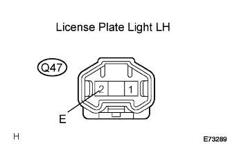
Measure the resistance according to the value(s) in the table below.
- Standard resistance:
Tester Connection
Condition
Specified Condition
Q47-2 (E)- Body ground
Always
Below 1 Ω
|
|
||||
| OK | |
|
| 12. CHECK HARNESS AND CONNECTOR (LICENSE PLATE LIGHT RH - MAIN BODY ECU LH) |
- HINT:
- Perform the following inspection on the RH side.
Disconnect the Q44 license plate light RH connector.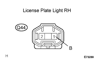
Measure the voltage according to the value(s) in the table below.
- Standard voltage:
Tester Connection
Condition
Specified Condition
Q44-1 (B) - Body ground
Engine switch off
Below 1 V
Q44-1 (B) - Body ground
Engine switch on (IG) and taillights on
10 to 14 V
|
|
||||
| OK | |
|
| 13. CHECK HARNESS AND CONNECTOR (LICENSE PLATE LIGHT RH - LICENSE PLATE LIGHT RH) |
- HINT:
- Perform the following inspection on the LH side.
Connect the Q44 license plate light RH connector.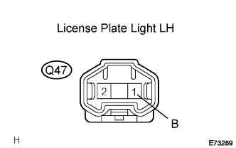
Disconnect the Q47 license plate light LH connector.
Measure the voltage according to the value(s) in the table below.
- Standard Voltage:
Tester Connection
Condition
Specified Condition
Q47-1 (B) - Body ground
Engine switch off
Below 1 V
Q47-1 (B) - Body ground
Engine switch on (IG) and taillights on
10 to 14 V
|
|
||||
| OK | ||
|
||
| ||
| 14. CHECK HARNESS AND CONNECTOR (LICENSE PLATE LIGHT LH - LICENSE PLATE LIGHT RH) |
Disconnect the Q44 license plate light RH connector.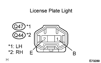
Disconnect the Q47 license plate light LH connector.
Measure the resistance according to the value(s) in the table below.
- Standard resistance:
Tester Connection
Condition
Specified Condition
Q44-2 (E) - Q47-1 (B)
Always
Below 1 Ω
Q44-2 (E) - Body ground
Always
10 kΩ or higher
|
|
||||
| OK | ||
|
||
| ||
| 15. CHECK HARNESS AND CONNECTOR (MAIN BODY ECU RH - BODY GROUND) |
Disconnect the RD main body ECU RH connector.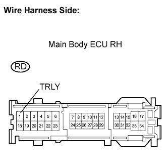
Measure the voltage according to the value(s) in the table below.
- Standard voltage:
Tester Connection
Condition
Specified Condition
RD-1 (TRLY) - Body ground
Always
10 to 14 V
|
|
||||
| OK | |
|
| 16. CHECK HARNESS AND CONNECTOR (MAIN BODY ECU RH - BODY GROUND) |
Connect the RD main body ECU RH connector.
Measure the voltage according to the value(s) in the table below.
- Standard voltage:
Tester Connection
Condition
Specified Condition
RD-1 (TRLY) - Body ground
Engine switch off
Below 1 V
RD-1 (TRLY) - Body ground
Engine switch on (IG) and taillights on
10 to 14 V
|
|
||||
| OK | |
|
| 17. INSPECT MAIN BODY ECU LH (COWL SIDE J/B LH) |
Disconnect the LJ main body ECU LH connector.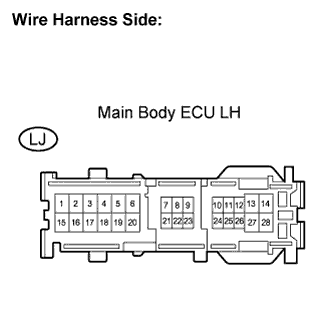
Measure the voltage according to the value(s) in the table below.
- Standard voltage:
Tester Connection
Condition
Specified Condition
LJ-24 - Body ground
Engine switch off
Below 1 V
LJ-24 - Body ground
Engine switch on (IG) and taillights on
10 to 14 V
|
|
||||
| OK | ||
|
||
| ||