Headlight (HI-BEAM) Circuit
Circuit diagnosis
DESCRIPTION
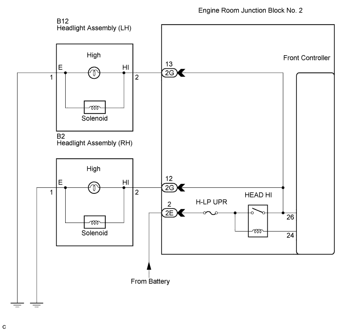
The front controller receives headlight HI switch information from the combination switch, and turns on the headlights.BI-function:
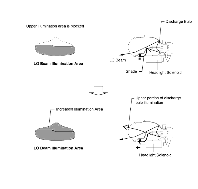
This function is activated by a HI beam turn ON signal from the front controller and activates the headlight solenoid built into the headlight unit to slide the shade down.
When the LO beam headlight is switched on, the upper illumination area of the discharge bulb is blocked by the shade and only the lower illumination area is used. When the HI beam is turned on, the headlight solenoid slides the shutter down to allow use of the upper illumination area, thus increasing the illumination area and improving visibility when the HI beam is on.

WIRING DIAGRAM
INSPECTION PROCEDURE
| 1. PERFORM ACTIVE TEST BY INTELLIGENT TESTER |

Connect the intelligent tester to the DLC3.
Turn the engine switch on (IG).
Turn the intelligent tester main switch on.
Select the item below in the ACTIVE TEST and then check the headlight operation.
ACTIVE TEST: Body No. 5 (Front Controller) Item
Test Details
Diagnostic Note
Light Head (High)
Headlight (High) ON / OFF
-
- OK:
- Headlight assembly illuminates.
|
|
||||

| OK | ||
 |
||
| ||
| 2. INSPECT FUSE (H-LP UPR) |
Remove the H-LP UPR fuse from the engine room No. 2 relay block.
Measure the resistance of the fuses.
- Standard resistance:
- Below 1 Ω
|
|
||||

| OK | |
 |
| 3. CHECK HARNESS AND CONNECTOR (ENGINE ROOM NO. 2 RELAY BLOCK - BATTERY) |
Disconnect the 2E relay block connector.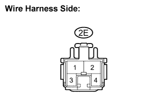
Measure the voltage according to the value(s) in the table below.
- Standard voltage:
Tester Connection
Condition
Specified Condition
2E-2 - Body ground
Always
10 to 14 V
|
|
||||
| OK | |
|
| 4. CHECK HARNESS AND CONNECTOR (ENGINE ROOM NO. 2 RELAY BLOCK - BODY GROUND) |
Check the wire harness between the headlight (LH) and engine room No. 2 relay block, and headlight (LH) and body ground.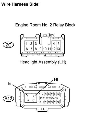
Disconnect the 2G relay block connector.
Disconnect the B12 headlight (LH) connector.
Measure the resistance according to the value(s) in the table below.
- Standard resistance:
Tester Connection
Condition
Specified Condition
2G-13 - B12-2 (HI)
Always
Below 1 Ω
2G-13 or B12-2 (HI) - Body ground
Always
10 kΩ or higher
B12-1 (E) - Body ground
Always
Below 1 Ω
Check the wire harness between the headlight (RH) and engine room No. 2 relay block, and headlight (RH) and body ground.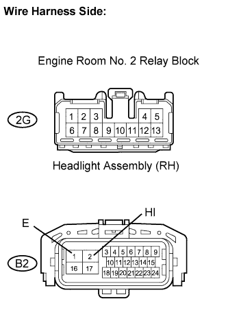
Disconnect the 2G relay block connector.
Disconnect the B2 headlight (RH) connector.
Measure the resistance according to the value(s) in the table below.
- Standard resistance:
Tester Connection
Condition
Specified Condition
2G-12 - B2-2 (HI)
Always
Below 1 Ω
2G-12 or B2-2 (HI) - Body ground
Always
10 kΩ or higher
B2-1 (E) - Body ground
Always
Below 1 Ω
|
|
||||
| OK | ||
|
||
| ||