Headlight Relay Circuit
Circuit diagnosis
DESCRIPTION
The headlight relay is turned ON by operating the headlight switch.When the theft deterrent system is activated, it causes the ECU to turn the headlight relay on and off repeatedly at approximately 0.25 second intervals to flash the headlights.
In this condition, if any of the following operations is performed, the ECU to turns the headlight relay off to stop the headlight from flashing:
- Unlock the driver door with a key.
- Turn the engine switch on (ACC) or on (IG).
- Unlock the doors with the wireless door lock control system.
WIRING DIAGRAM
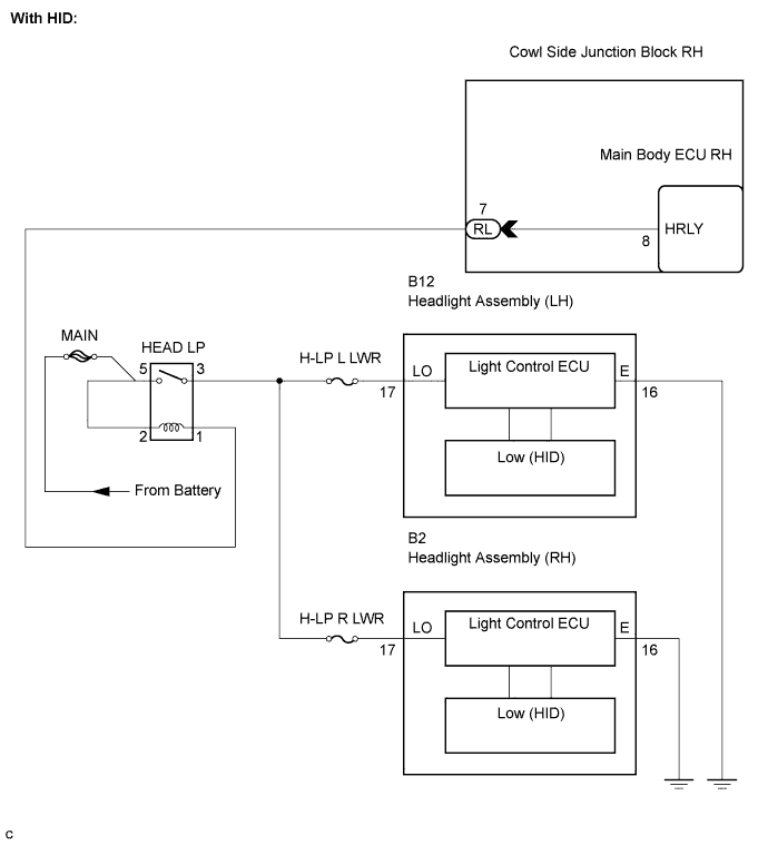

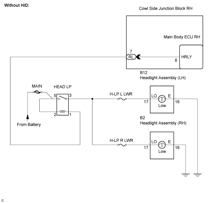
INSPECTION PROCEDURE
| 1. PERFORM ACTIVE TEST BY INTELLIGENT TESTER |

Connect the intelligent tester to the DLC3.
Turn the engine switch on (IG).
Turn the intelligent tester main switch on.
Select the item below in the ACTIVE TEST and then check the relay operation.
ACTIVE TEST: Main Body (Main Body ECU RH) Item
Test Details
Diagnostic Note
Headlight Relay
Headlight relay ON / OFF
-
- OK:
- Headlight assembly (low) illuminates.
|
|
||||

| NG | |
 |
| 2. INSPECT FUSE (H-LP L LWR, H-LP R LWR) |
Remove the H-LP L LWR fuse from the engine room No. 2 relay block .
Remove the H-LP R LWR fuse from the engine room No. 2 relay block .
Measure the resistance of the fuses.
- Standard resistance:
- Below 1 Ω
|
|
||||
| OK | |
|
| 3. INSPECT HEAD LP RELAY |
Remove the HEAD LP relay from the engine room No. 1 relay block.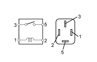
Measure the resistance according to the value(s) in the table below.
- Standard resistance:
Tester Connection
Specified Condition
3 - 5
10 kΩ or higher
3 - 5
Below 1 Ω
(When battery voltage is applied to terminals 1 and 2)
|
|
||||
| OK | |
|
| 4. CHECK HARNESS AND CONNECTOR (MAIN BODY ECU RH - BATTERY) |
Disconnect the RL main body ECU RH connector.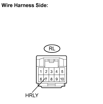
Measure the voltage according to the value(s) in the table below.
- Standard voltage:
Tester Connection
Condition
Specified Condition
RL-7 (HRLY) - Body ground
Always
10 to 14 V
|
|
||||
| OK | |
|
| 5. CHECK HARNESS AND CONNECTOR (HEADLIGHT (LOW LH OR LOW RH) - BATTERY AND BODY GROUND) |
Check the wire harness between the headlight (Low LH) and battery, and the headlight (Low LH) and body ground.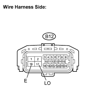
Disconnect the B12 headlight connector.
Measure the voltage and resistance according to the value(s) in the table below.
- Standard voltage:
Tester Connection
Condition
Specified Condition
B12-17 (LO) - Body ground
Turn the light control switch to the ON (HEAD) position.
10 to 14 V
- Standard resistance:
Tester Connection
Condition
Specified Condition
B12-16 (E) - Body ground
Always
Below 1 Ω
Check the wire harness between the headlight (Low RH) and battery, and the headlight (Low RH) and body ground.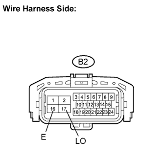
Disconnect the B2 headlight connector.
Measure the voltage and resistance according to the value(s) in the table below.
- Standard voltage:
Tester Connection
Condition
Specified Condition
B2-17 (LO) - Body ground
Turn the light control switch to the ON (HEAD) position.
10 to 14 V
- Standard resistance:
Tester Connection
Condition
Specified Condition
B2-16 (E) - Body ground
Always
Below 1 Ω
|
|
||||
| NG | |
|
| 6. CHECK HARNESS AND CONNECTOR (HEADLIGHT (LOW LH OR LOW RH) - HEAD LP RELAY) |
Check the harness and the connectors between the headlight (Low LH or Low RH) and the HEAD LP relay.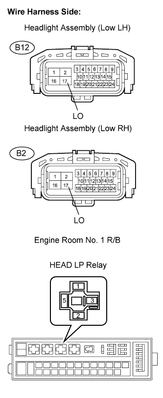
Disconnect the B12 light connector.
Remove the HEAD LP relay from the engine room No. 1 relay block.
Measure the resistance according to the value(s) in the table below.
- Standard resistance:
- Check for open:
Headlight Assembly
Tester Connection
Specified Condition
LH
B12-17 (LO) - HEAD LP relay terminal (3)
Below 1 Ω
RH
B2-17 (LO) - HEAD LP relay terminal (3)
Below 1 Ω
- Check for short:
Headlight Assembly
Tester Connection
Specified Condition
LH
B12-17 (LO) or HEAD LP relay terminal (3) - Body ground
10 kΩor higher
RH
B2-17 (LO) or HEAD LP relay terminal (3) - Body ground
10 kΩor higher
|
|
||||
| OK | ||
 |
||
| ||