Cruise Control Switch Circuit
Circuit diagnosis
DESCRIPTION
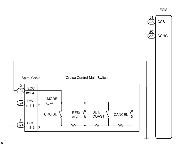
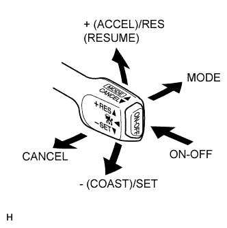
The cruise control main switch operates 8 functions: SET, -(COAST), TAP-DOWN, RES (RESUME), + (ACCEL), TAP-UP, CANCEL, and MODE. The SET, TAP-DOWN, and - (COAST) functions, and the RES (RESUME), TAP-UP, and + (ACCEL) functions are operated with the same switch. The cruise control main switch is an automatic return type switch which turns on only while operating it in the direction of each arrow and turns off after releasing it. The internal contact point of the cruise control main switch is turned on with the switch operation. The ECM then reads the voltage value that has been changed by the switch operation to control MODE, SET, - (COAST), RES (RESUME), + (ACCEL), and CANCEL. The dynamic radar cruise control system has two cruise control modes: the constant speed control mode and vehicle-to-vehicle distance control mode.- The vehicle-to-vehicle distance control mode is always selected when starting up the dynamic radar cruise control system.
- The operation of the constant speed control mode is the same as that for a conventional cruise control system.
WIRING DIAGRAM

INSPECTION PROCEDURE
| 1. READ VALUE ON INTELLIGENT TESTER |

 |
Connect the intelligent tester to the DLC3.
Turn the engine switch on (IG) and turn the intelligent tester main switch on.
Check the DATA LIST for proper functioning of the cruise control main switch.
ECM (Cruise control): Item
Measurement Item / Display (Range)
Normal Condition
Diagnostic Note
MAIN SW (MAIN)
Main switch signal (Main CPU) / ON or OFF
ON: Main switch ON (Pushed on)
OFF: Main switch OFF (Pushed off)
-
CANCEL SW
CANCEL switch signal / ON or OFF
ON: CANCEL switch ON
OFF: CANCEL switch OFF
-
SET/COAST SW
SET/COAST switch signal / ON or OFF
ON: - (COAST)/SET switch ON
OFF: - (COAST)/SET switch OFF
-
RES/ACC SW
RES/ACC switch signal / ON or OFF
ON: + (ACCEL)/RES (RESUME) switch ON
OFF: + (ACCEL)/RES (RESUME) switch OFF
-
- OK:
- When the cruise control main switch is operated, the display changes as shown above.
Result: Result
Proceed to
OK
A
NG (all items are defective)
B
NG (1 to 3 items are defective)
C
|
|
||||
|
|
||||

| B | |
 |
| 2. INSPECT CRUISE CONTROL MAIN SWITCH |
Disconnect the cruise control main switch connector.
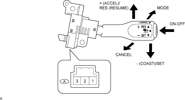
Measure the resistance according to the value(s) in the table below.
- Standard resistance:
Tester Connection
Switch Condition
Specified Condition
A-1 (ECC) - A-2 (R/N), A-1 (ECC) - A-3 (CCS)
Neutral
10 kΩ or higher
A-1 (ECC) - A-3 (CCS)
+ (ACCEL)/RES (RESUME)
216 to 264 Ω
A-1 (ECC) - A-3 (CCS)
- (COAST)/SET
567 to 693 Ω
A-1 (ECC) - A-3 (CCS)
CANCEL
1,386 to 1,694 Ω
A-1 (ECC) - A-3 (CCS)
Main Switch off
10 kΩ or higher
A-1 (ECC) - A-3 (CCS)
Main Switch on
Below 1 Ω
A-1 (ECC) - A-2 (R/N)
Main Switch on and MODE Switch on
Below 1 Ω
|
|
||||
| OK | |
|
| 3. INSPECT SPIRAL CABLE |
- NOTICE:
- The spiral cable is an important part of the SRS airbag system. Incorrect removal or installation of the spiral cable may prevent the airbag from deploying. Be sure to read the page shown in the brackets.
- HINT:
- Removal (Click here)
- Installation (Click here)
- Removal (Click here)
Remove the spiral cable.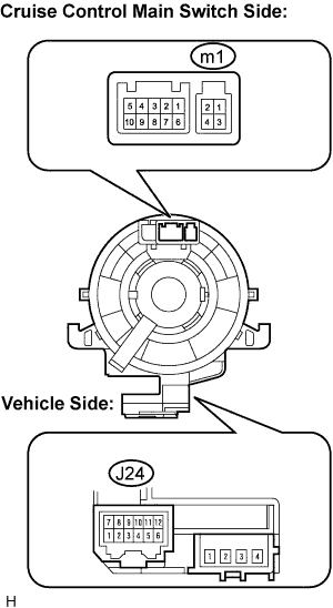
Measure the resistance according to the value(s) in the table below.
Standard resistance Tester Condition
Spiral Cable Position
Specified Condition
m1-1 - J24-7
Center
Below 1 Ω
2.5 rotations to the left
2.5 rotation to the right
m1-3 - J24-1
Center
Below 1 Ω
2.5 rotation to the left
2.5 rotation to the right
m1-4 - J24-2
Center
Below 1 Ω
2.5 rotation to the left
2.5 rotation to the right
- HINT:
- The spiral cable makes a maximum of approximately 5 rotations.
|
|
||||
| OK | |
|
| 4. CHECK WIRE HARNESS (SPIRAL CABLE - ECM) |
Measure the resistance according to the value(s) in the table below.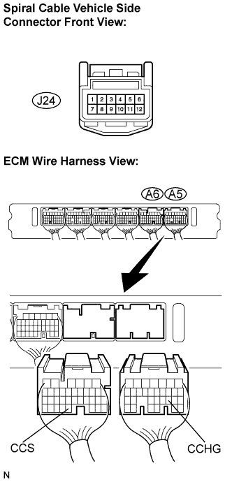
- Standard resistance:
Tester Connection
Condition
Specified Condition
J24-1 - A6-31 (CCS)
Always
Below 1 Ω
J24-7 - A5-20 (CCHG)
Always
Below 1 Ω
J24-1 - Body ground
Always
10 kΩ or higher
J24-7 - Body ground
Always
10 kΩ or higher
|
|
||||
| OK | |
|
| 5. CHECK WIRE HARNESS (SPIRAL CABLE - BODY GROUND) |
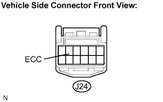 |
Measure the resistance according to the value(s) in the table below.
- Standard resistance:
Tester Connection
Condition
Specified Condition
J24-2 - Body ground
Always
Below 1 Ω
|
|
||||
| OK | ||
 |
||
| ||