TERMINALS OF ECU
System information
| Combination Meter Assembly |
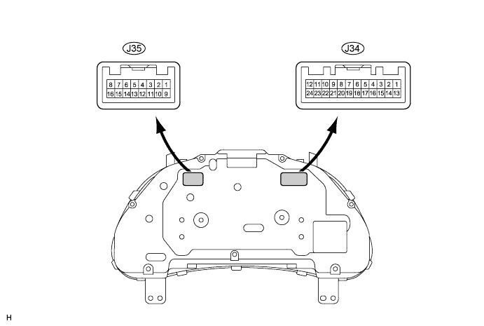

| Symbols (Terminal No.) |
Wiring Color |
Terminal Description |
Condition |
Specified Condition |
| E2 (J34-1) - Body Ground |
W-B - Body ground |
Ground |
Always |
Below 1 V |
| FE (J34-2) - Body ground |
BR - Body ground |
Ground (Fuel ground) |
Always |
Below 1 V |
| +S (J34-5) - Body ground |
P - Body ground |
Speed signal (Output) |
Turn the wheel slowly |
Pulse generation (See waveform 1) |
| MPX+ (J34-6) - Body ground |
BR - Body ground |
Multiplex communication signal |
- |
- |
| TC (J34-8) - Body ground |
P - Body ground |
Light control rheostat signal |
Engine switch on (IG), the light control rheostat knob is at the MAX. position (turns fully clockwise) |
4 to 6 V |
| Engine switch on (IG), the light control rheostat knob is at the MIN. position (turns fully counterclockwise) |
Below 1 V |
|||
| ILL+ (J34-9) - Body ground |
V - Body ground |
Light control rheostat signal |
Engine switch on (IG), combination switch is except on OFF |
4 to 6 V |
| B (J34-11) - Body ground |
G - Body ground |
Turn indicator light signal |
Engine switch on (IG), turn signal LH indicator light OFF |
Below 1 V |
| Engine switch on (IG), turn signal LH indicator light ON |
10 to 14 V |
|||
| EFI (J34-12) - Body ground |
O - Body ground |
Ignition switch signal |
Engine switch off |
Below 1 V |
| Engine switch on (IG) |
10 to 14 V |
|||
| ES (J34-13) - Body ground |
W-B - Body ground |
Ground (Signal ground) |
Always |
Below 1 V |
| ET (J34-14) - Body ground |
Y - Body ground |
Ground (Rheostat ground) |
Always |
Below 1 V |
| S (J34-16) - Body ground |
W - Body ground |
Tachometer signal |
Engine switch on (IG), engine idle speed |
Pulse generation (See waveform 2) |
| SI (J34-17) - Body ground |
V - Body ground |
Speed signal (Input) |
Engine switch on (IG), turn the wheel slowly |
Pulse generation (See waveform 1) |
| MPX- (J34-18) - Body ground |
BR - Body ground |
Multiplex communication signal |
- |
- |
| FR (J34-19) - Body ground |
SB - Body ground |
Fuel signal |
Engine switch on (IG), fuel level is FULL |
Below 1 V |
| Engine switch on (IG), fuel level is EMPTY |
4 to 7 V |
|||
| MSSL (J34-20) - Body ground |
V - Body ground |
Steering pad switch signal |
Engine switch on (IG), DISP switch off |
4 to 6 V |
| Engine switch on (IG), DISP switch ON |
Below 1 V |
|||
| TR (J34-21) - Body ground |
B - Body ground |
Light control rheostat signal |
Engine switch on (IG), the light control rheostat knob is at the MIN. position (turns fully counterclockwise). |
Below 1 V |
| Engine switch on (IG), the light control rheostat knob is at the MAX. position (turns fully clockwise). |
4 to 6 V |
|||
| B (J34-23) - Body ground |
L - Body ground |
Battery |
Always |
10 to 14 V |
| B (J34-24) - Body ground |
LG - Body ground |
Battery |
Always |
10 to 14 V |
| PBLT (J35-3) - Body ground |
P - Body ground |
Passenger seat belt warning light signal |
Sit in the passenger seat, engine switch on (IG), passenger seat belt fastened |
10 to 14 V |
| Sit in the passenger seat, engine switch on (IG), p- belt warning light blinks |
Pulse generation (See waveform 3) |
|||
| P/SB (J35-4) - Body ground |
L - Body ground |
Passenger seat inner belt signal |
Engine switch on (IG), passenger seat belt unfastened |
10 to 14 V |
| Engine switch on (IG), passenger seat belt fastened |
Below 1 V |
|||
| RSEL (J35-5) - Body ground |
GR - Body ground |
Satellite switch RH signal |
Engine switch on (IG), satellite switch RH off |
4 to 6 V |
| Engine switch on (IG), satellite switch RH ON |
Below 1 V |
|||
| LSEL (J35-6) - Body ground |
O - Body ground |
Satellite switch LH signal |
Engine switch on (IG), satellite switch LH off |
4 to 6 V |
| Engine switch on (IG), satellite switch LH ON |
Below 1 V |
|||
| SET (J35-7) - Body ground |
V - Body ground |
Satellite switch ON/OFF signal |
Engine switch on (IG), satellite switch ON/OFF off |
4 to 6 V |
| Engine switch on (IG), satellite switch ON/OFF ON |
Below 1 V |
|||
| ILL- (J34-9) - Body ground |
W - Body ground |
Illumination signal |
Engine switch on (IG) |
10 to 14 V |
| B (J35-10) - Body ground |
R - Body ground |
Turn indicator light signal |
Engine switch on (IG), turn signal RH indicator light OFF |
Below 1 V |
| Engine switch on (IG), turn signal RH indicator light ON |
10 to 14 V |
|||
| EFI (J35-11) - Body ground |
LG - Body ground |
Check engine indicator light signal |
Engine switch on (IG), CHECK ENGINE warning light ON |
Below 1 V |
| Engine switch on (IG), CHECK ENGINE warning light OFF |
10 to 14 V |
|||
| SW (J35-15) - Body ground |
LG - Body ground |
Brake fluid level warning light signal |
Engine switch on (IG), BRAKE warning light OFF |
10 to 14 V |
| Engine switch on (IG), BRAKE warning light ON |
Below 1.5 V |
Waveform 1 (Reference) : Using an oscilloscope: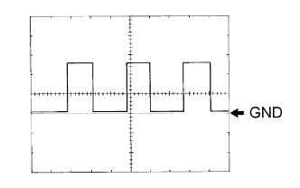
OK: Item
Condition
Tool setting
5 V/DIV., 20 ms./DIV.
Vehicle condition
Driving at approx. 20 km/h (12 mph)
- HINT:
- As vehicle speed increases, the cycle of the signal waveform narrows.
Waveform 2 (Reference) : Using an oscilloscope: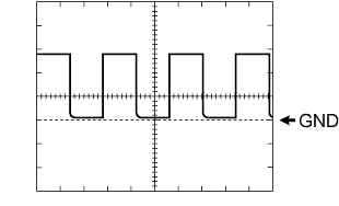
OK: Item
Condition
Tool setting
5 V/DIV., 10 ms./DIV.
Vehicle condition
Engine idle speed
Waveform 3 (Reference) : Using an oscilloscope:
OK: Item
Condition
Tool setting
5 V/DIV., 200 ms./DIV.
Vehicle condition
Engine switch on (IG), p-belt warning light blinks
| CLOCK ASSEMBLY (without NAVIGATION SYSTEM) |

| Symbols (Terminal No.) |
Wiring Color |
Terminal Description |
Condition |
Specified Condition |
| ILL+ (J54-3) - Body ground |
G - Body ground |
Illumination Signal |
Combination switch OFF |
Below 1 V |
| Combination switch Head |
10 to 14 V |
|||
| IG+ (J54-4) - Body ground |
B - Body ground |
Ignition Switch Signal |
Engine switch off |
Below 1 V |
| Engine switch on (IG) |
10 to 14 V |
|||
| ACC (J54-5) - Body ground |
O - Body ground |
Ignition Switch Signal |
Engine switch off |
Below 1 V |
| Engine switch on (IG) |
10 to 14 V |
|||
| E (J54-8) - Body ground |
W-B - Body ground |
Ground |
Always |
Below 1 V |
| ILL-(J54-10) - Body ground |
LG - Body ground |
Illumination Signal |
Engine switch on (IG), combination switch Head, and light control rheostat position MAX. |
Pulse generation (See waveform) |
| B (J54-14) - Body ground |
LG - Body ground |
Battery |
Always |
10 to 14 V |
Waveform (Reference) : Using an oscilloscope:
OK: Item
Condition
Tool setting
5 V/DIV., 200 ms./DIV.
Vehicle condition
Engine switch on (IG), light control rheostat is in the MID. position.
| CLOCK ASSEMBLY (with NAVIGATION SYSTEM) |

| Symbols (Terminal No.) |
Wiring Color |
Terminal Description |
Condition |
Specified Condition |
| E (J53-2) - Body ground |
W-B - Body ground |
Ground |
Always |
Below 1 V |
| ILL+ (J53-4) - Body ground |
G - Body ground |
Illumination Signal |
Combination switch OFF |
Below 1 V |
| Combination switch Head |
10 to 14 V |
|||
| ACC (J53-5) - Body ground |
W-B - Body ground |
Ignition Switch Signal |
Engine switch off |
Below 1 V |
| Engine switch on (IG) |
10 to 14 V |
|||
| +B (J53-6) - Body ground |
BR - Body ground |
Battery |
Always |
10 to 14 V |
| ILL-(J53-10) - Body ground |
W - Body ground |
Illumination Signal |
Engine switch on (IG), combination switch Head, and light control rheostat position MAX. |
Pulse generation (See waveform) |
| IG (J53-11) - Body ground |
B - Body ground |
Ignition Switch Signal |
Engine switch off |
Below 1 V |
| Engine switch on (IG) |
10 to 14 V |
Waveform (Reference) : Using an oscilloscope:
OK: Item
Condition
Tool setting
5 V/DIV., 200 ms./DIV.
Vehicle condition
Engine switch on (IG), light control rheostat is in the MID. position.
| COMBINATION METER INNER CIRCUIT |
*2: with Navigation System
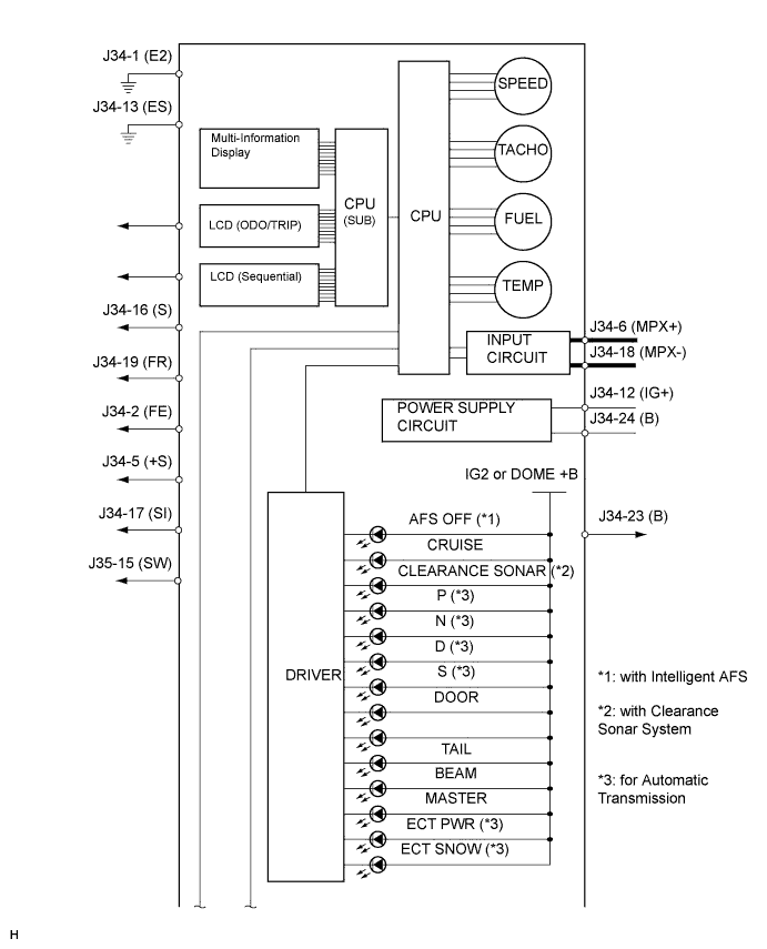
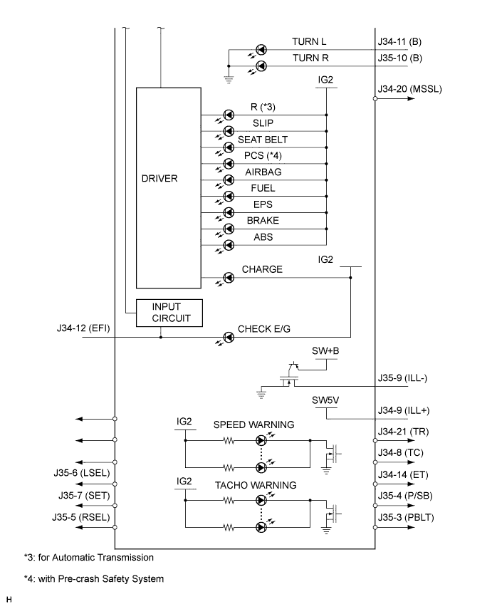
| Terminals No. |
Wire harness side |
|
| J34 |
1 |
Ground |
| 2 |
Ground (Fuel Ground) |
|
| 3 |
- |
|
| 4 |
- |
|
| 5 |
Each part that uses speed signal |
|
| 6 |
Multiplex Communication Line (MPX+) |
|
| 7 |
- |
|
| 8 |
Light Control Rheostat (TC) |
|
| 9 |
Light Control Rheostat (ILL+) |
|
| 10 |
- |
|
| 11 |
Turn Signal Flasher (B) |
|
| 12 |
MET Fuse |
|
| 13 |
Ground (Signal Ground) |
|
| 14 |
Light Control Rheostat (ET) |
|
| 15 |
- |
|
| 16 |
ECM (S) |
|
| 17 |
ABS & Traction Actuator Assembly |
|
| 18 |
Multiplex Communication Line (MPX-) |
|
| 19 |
Fuel Sender Gauge Assembly (FR) |
|
| 20 |
Steering Pad Switch (DISP) |
|
| 21 |
Light Control Rheostat (TR) |
|
| 22 |
- |
|
| 23 |
DOME Fuse |
|
| 24 |
MPX-B Fuse |
|
| J35 |
1 |
- |
| 2 |
- |
|
| 3 |
Integration Control & Panel Assembly (*1)/Multi-display (*2) |
|
| 4 |
Passenger Side Front Seat Inner Belt Assembly |
|
| 5 |
Satellite Switch (RSEL) |
|
| 6 |
Satellite Switch (LSEL) |
|
| 7 |
Satellite Switch (SET) |
|
| 8 |
- |
|
| 9 |
Illumination Parts |
|
| 10 |
Turn Signal Flasher (B) |
|
| 11 |
- |
|
| 12 |
ECM (EFI) |
|
| 13 |
- |
|
| 14 |
- |
|
| 15 |
Brake Fluid Level Warning Switch |
|
| 16 |
- |
|