B1461/61
Diagnostic trouble codes
DESCRIPTION
The smog ventilation sensor detects NOx in the emission gas and transmits signals to the A/C amplifier. Based on the signals, the A/C amplifier performs automatic air inlet control (FRESH, FRESH / RECIRCULATION, or RECIRCULATION mode).| DTC No. |
DTC Detection Condition |
Trouble Area |
| B1461/61 |
Open or short in emission gas NOx sensor circuit |
|
WIRING DIAGRAM
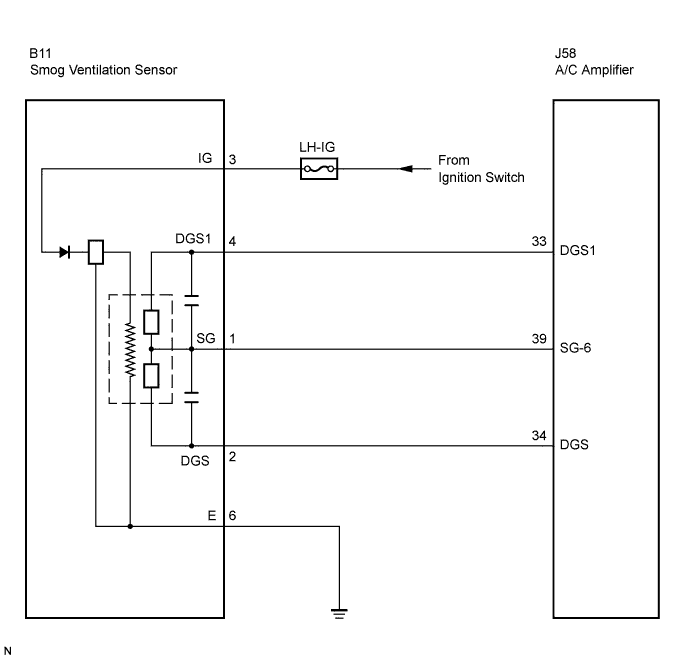

INSPECTION PROCEDURE
| 1. INSPECT FUSE (LH-IG) |

Remove the LH-IG fuse from the cowl side junction block LH.
Measure the resistance according to the value(s) in the table below.
- Standard resistance:
Tester Item
Condition
Specified Condition
LH-IG fuse
Always
Below 1 Ω
|
|
||||

| OK | |
 |
| 2. READ VALUE OF INTELLIGENT TESTER |
Connect the intelligent tester to the DLC3.
Turn the engine switch on (IG) and turn the intelligent tester main switch on.
Allow exhaust gas (NOx) to travel to the sensing portion of the smog ventilation sensor.
Select the item below in the Data List, and read the display on the intelligent tester.
| Item |
Measure Item / Display (Range) |
Normal Condition |
Diagnostic Note |
| Emission Gas Sensor (Emiss Gas Sens) |
Emission gas NOx sensor / Min.: 0, Max.: 255 |
Smog ventilation sensor value increases as gas amount increases |
- |
- OK:
- The display is as specified in the normal condition column.
- Result:
Result
Proceed to
NG
A
OK (When troubleshooting according to the PROBLEM SYMPTOMS TABLE)
B
OK (When troubleshooting according to the DTC)
C
|
|
||||
|
|
||||
| A | |
|
| 3. CHECK WIRE HARNESS (SMOG VENTILATION SENSOR - BODY GROUND) |
Disconnect the smog ventilation sensor connector.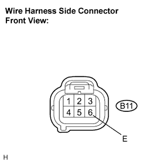
Measure the resistance according to the value(s) in the table below.
- Standard resistance:
Tester Connection
Condition
Specified Condition
B11-6 (E) - Body ground
Always
Below 1 Ω
|
|
||||
| OK | |
|
| 4. CHECK WIRE HARNESS (SMOG VENTILATION SENSOR - BATTERY) |
Disconnect the smog ventilation sensor connector.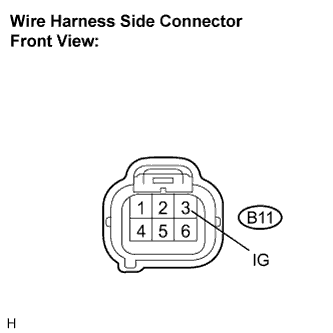
Measure the voltage according to the value(s) in the table below.
- Standard voltage:
Tester Connection
Condition
Specified Condition
B11-3 (IG) - Body ground
Engine switch on (IG)
10 to 14 V
Engine switch off
Below 1 V
|
|
||||
| OK | |
|
| 5. INSPECT SMOG VENTILATION SENSOR |
Remove the smog ventilation sensor.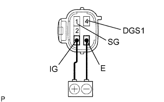
Apply battery voltage between terminals 3 (IG) and 6 (E).
Allow exhaust gas (NOx) to travel to the sensing portion of the smog ventilation sensor, and measure the resistance between terminals 1 (SG) and 4 (DGS1).
- OK:
- When the sensor is exposed to the exhaust gas, the resistance increases.
- HINT:
- The resistance before blowing exhaust gas is 10 kΩ to 40 kΩ.
|
|
||||
| OK | |
|
| 6. CHECK WIRE HARNESS (SMOG VENTILATION SENSOR - A/C AMPLIFIER) |
Disconnect the exhaust gas sensor connector.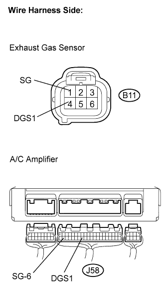
Disconnect the A/C amplifier connector.
Measure the resistance according to the value(s) in the table below.
- Standard resistance:
Tester Connection
Condition
Specified Condition
B11-1 (SG) - J58-39 (SG-6)
Always
Below 1 Ω
B11-4 (DGS1) - J58-33 (DGS1)
Always
Below 1 Ω
J58-39 (SG-6) - Body ground
Always
10 kΩ or higher
J58-33 (DGS1) - Body ground
Always
10 kΩ or higher
|
|
||||
| OK | ||
 |
||
| ||