B1451/51
Diagnostic trouble codes
DESCRIPTION
In this circuit, the compressor receives a refrigerant compression demand signal from the air conditioning amplifier.Based on this signal, the compressor changes the amount of compressor output.
| DTC No. |
DTC Detection Condition |
Trouble Area |
| B1451/51 |
Open or short in solenoid of the externally changeable compressor circuit |
|
WIRING DIAGRAM
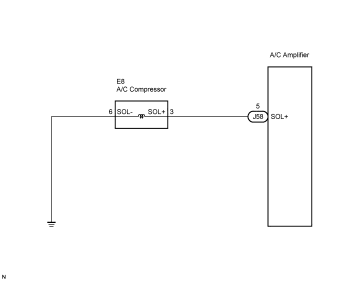

INSPECTION PROCEDURE
| 1. INSPECT A/C COMPRESSOR |

Disconnect the A/C compressor connector.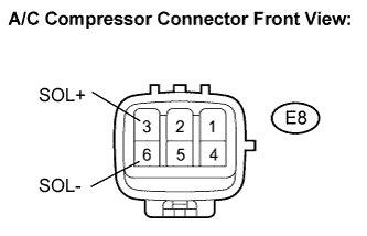
Measure the resistance according to the value(s) in the table below.
- Standard resistance:
Tester Connection
Condition
Specified Condition
E8-3 (SOL+) - E8-6 (SOL-)
20°C (68°F)
10 to 11 Ω
|
|
||||

| OK | |
 |
| 2. CHECK WIRE HARNESS (A/C COMPRESSOR - BODY GROUND) |
Disconnect the A/C compressor connector.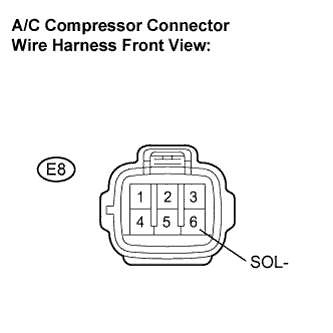
Measure the resistance according to the value(s) in the table below.
- Standard resistance:
Tester Connection
Condition
Specified Condition
E8-6 (SOL-) - Body ground
Always
Below 1 Ω
|
|
||||
| OK | |
|
| 3. CHECK WIRE HARNESS (A/C COMPRESSOR - A/C AMPLIFIER) |
Disconnect the A/C compressor connector.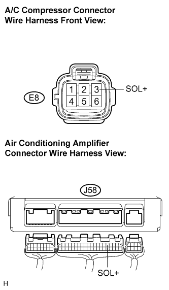
Disconnect the A/C amplifier connector.
Measure the resistance according to the value(s) in the table below.
- Standard resistance:
Tester Connection
Condition
Specified Condition
J58-5 (SOL+) - E8-3 (SOL+)
Always
Below 1 Ω
J58-5 (SOL+) - Body ground
Always
10 kΩ or higher
- Result:
Result
Proceed to
NG
A
OK (When troubleshooting according to the PROBLEM SYMPTOMS TABLE)
B
OK (When troubleshooting according to the DTC)
C
|
|
||||
|
|
||||
| A | ||
 |
||
| ||