Millimeter Wave Radar Sensor Power Source Circuit
Circuit diagnosis
DESCRIPTION
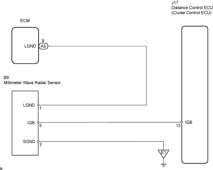
This circuit provides power to the millimeter wave radar sensor. The millimeter wave radar sensor emits radio waves towards an object in front and measures the distance and direction of the object by receiving the beam reflections. Based on the reflections, the sensor calculates the difference in speed between the vehicle and the object in front. This data is transmitted to the distance control ECU (cruise control ECU). The ECU recognizes the millimeter wave radar sensor via terminals LGND. If an open circuit occurs in the wire harness between terminals LGND, the ECM cannot recognize the millimeter wave radar sensor. The ECM will stop the control of the vehicle-to-vehicle distance control mode and only the constant speed control mode can be used.WIRING DIAGRAM

INSPECTION PROCEDURE
| 1. CHECK DISTANCE CONTROL ECU (IGB VOLTAGE) |

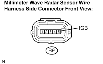 |
Disconnect the B9 sensor connector.
Measure the voltage according to the value(s) in the table below.
- Standard voltage:
Tester Connection
Condition
Specified Condition
B9-5 (IGB) - Body ground
Engine switch on (IG)
10 to 14 V
|
|
||||

| OK | |
 |
| 2. CHECK WIRE HARNESS (MILLIMETER WAVE RADAR SENSOR - ECM AND BODY GROUND) |
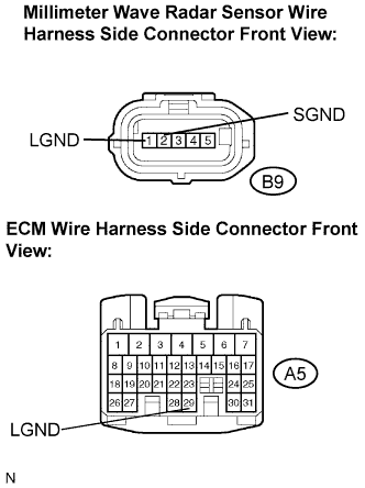 |
Disconnect the B9 sensor connector.
Disconnect the A5 ECM connector.
Measure the resistance according to the value(s) in the table below.
- Standard resistance:
Tester Connection
Specified Condition
A5-29 (LGND) - B9-1 (LGND)
Below 1 Ω
B9-1 (LGND) - Body ground
10 kΩ or higher
B9-2 (SGND) - Body ground
Below 1 Ω
|
|
||||

| OK | ||
 |
||
| ||
| 3. CHECK WIRE HARNESS (MILLIMETER WAVE RADAR SENSOR - DISTANCE CONTROL ECU) |
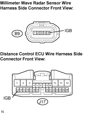 |
Disconnect the B9 sensor connector.
Disconnect the J17 ECU connector.
Measure the resistance according to the value(s) in the table below
- Standard resistance:
Tester Connection
Specified Condition
B9-5 (IGB) - J17-13 (IGB)
Below 1 Ω
J17-13 (IGB) - Body ground
10 kΩ or higher
|
|
||||
| OK | ||
|
||
| ||