Distance Control Switch Circuit
Circuit diagnosis
DESCRIPTION
The distance control switch sets the vehicle-to-vehicle distance control mode. The distance control switch is installed in the steering pad switch. The vehicle-to-vehicle distance set value can be changed by operating the steering pad switch (distance control switch) while the dynamic radar cruise control system is in operation. The steering pad switch uses the BEAN to communicate with each ECU. Therefore, it does not have a direct connection with the ECM. If there are any malfunctions in the communication line of the steering pad switch, one or more DTCs in the multiplex communication system are output.WIRING DIAGRAM
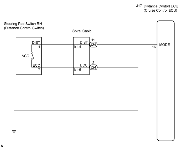

INSPECTION PROCEDURE
- NOTICE:
- When the distance control ECU is replaced with a new one, initialization must be performed (Click here).
| 1. INSPECT DISTANCE CONTROL ECU |

Turn the engine switch on (IG).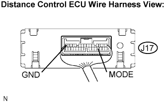
Measure the voltage according to the value(s) in the table below.
- Standard voltage:
Tester Connection
Condition
Specified Condition
J17-16 (MODE) - J17-12 (GND)
Distance control switch ON (pushed)
0 to 2 V
Distance control switch OFF (pushed)
10 to 14 V
|
|
||||

| NG | |
 |
| 2. INSPECT DISTANCE CONTROL ECU CIRCUIT |
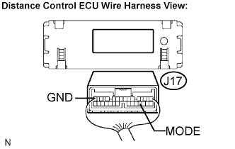 |
Disconnect the J17 connector.
Measure the resistance according to the value(s) in the table below.
- Standard resistance:
Tester connection
Condition
Specified condition
J17-16 (MODE) - Body ground
Distance control switch ON (pushed)
Below 1 Ω
Distance control switch OFF (pushed)
10 kΩ or higher
|
|
||||
| NG | |
|
| 3. INSPECT STEERING PAD SWITCH ASSEMBLY |
Remove the steering pad (Click here).
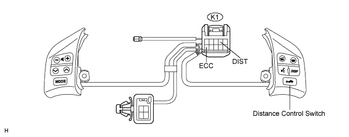
Disconnect K1 connector from the spiral cable.
Measure the resistance according to the value(s) in the table below.
- Standard resistance:
Tester Connection
Condition
Specified Condition
K1-4 (DIST) - K1-6 (ECC)
Distance control switch ON (pushed)
Below 2.5 Ω
K1-4 (DIST) - K1-6 (ECC)
Distance control switch OFF (pushed)
10 kΩ or higher
|
|
||||
| OK | |
|
| 4. CHECK HARNESS AND CONNECTOR (ECM - SPIRAL CABLE) |
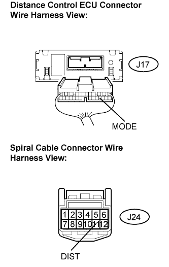 |
- NOTICE:
- The spiral cable is an important part of the SRS airbag system. Incorrect removal or installation of the spiral cable may prevent the airbag from deploying. Be sure to read the page shown in the brackets.
- HINT:
- Removal (Click here)
- Installation (Click here)
- Removal (Click here)
Remove the spiral cable.
Disconnect the J17 connector from the distance control ECU.
Measure the resistance according to the value(s) in the table below.
- Standard resistance:
Tester Connection
Specified Condition
J24-11 (DIST) - J17-16 (MODE)
Below 1 Ω
J24-11 - Body ground
10 kΩ or higher
|
|
||||
| OK | ||
 |
||
| ||