DISASSEMBLY
Removal / installation
- NOTICE:
- When using a vise, do not overtighten.
| 1. REMOVE STEERING LOCK ACTUATOR ASSEMBLY |

Using a center punch, mark the center of the 2 tapered-head bolts.
Using a 3 to 4 mm (0.12 to 0.16 in.) drill, drill a hole in the 2 bolts.
Using a screw extractor, remove the 2 bolts and steering lock actuator assembly from the steering column assembly.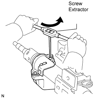

| 2. REMOVE TILT STEERING SUPPORT |
Remove the bolt and the tilt steering support from the steering column tube assembly.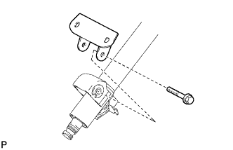
| 3. REMOVE BREAK AWAY COLLAR SUB-ASSEMBLY |
Remove the 2 brake away collar sub-assemblies and the 2 brake away capsules from the brake away bracket.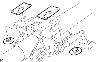
| 4. REMOVE TILT LEVER RETURN SPRING |
Using SST, remove the tilt lever return spring from the brake away bracket and steering tilt lever.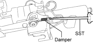
- SST
- 09921-00010
- NOTICE:
- Do not drop the damper from the tilt lever return spring.
- HINT:
- Use a shop rag or a piece of cloth to prevent the spring from flying out.
| 5. REMOVE TILT STEERING JUMP UP SPRING |
Secure the brake away bracket in a vise.
Using pliers, remove the tilt jump up spring from the brake away bracket as shown in the illustration.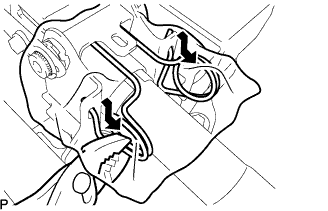
- HINT:
- Use a shop rag or a piece of cloth to prevent the spring from flying out.
| 6. REMOVE NO. 1 TILT STEERING SUPPORT REINFORCE |
Turn the steering tilt lever to the lock position.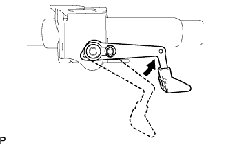
Remove the No. 2 tilt lever lock bolt and No. 1 tilt steering support reinforce from the steering telescopic lever.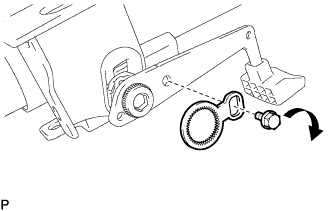
- NOTICE:
- The No. 2 steering tilt lever bolt is a left-hand threaded bolt.
| 7. REMOVE BREAK AWAY BRACKET |
Using a chisel and hammer, unstake the No. 1 tilt steering adjusting nut.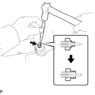
Remove the tilt steering adjusting nut.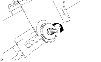
- NOTICE:
- Do not remove the No. 1 tilt lever lock bolt.
- The steering tilt steering adjusting nut is a left-hand threaded nut.
- Do not remove the No. 1 tilt lever lock bolt.
Remove the tilt steering rotor, thrust needle roller bearing, and steering column tube stopper (without groove).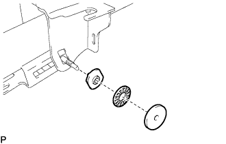
Remove the No. 1 tilt lever lock bolt, steering tilt lever, and steering column tube stopper (with groove).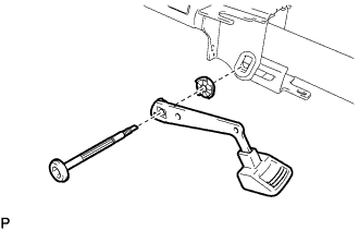
- NOTICE:
- The No. 1 tilt lever lock bolt is a left-hand threaded bolt.
Remove the brake away bracket.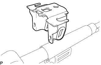
| 8. REMOVE TILT STEERING PAWL ASSEMBLY |
Remove the tilt steering pawl from the steering column tube assembly upper.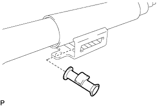
| 9. REMOVE STEERING MAIN SHAFT SNAP RING |
Secure the steering column tube assembly upper in a vise.
Using a snap ring expander, remove the steering main shaft snap ring from the steering main shaft.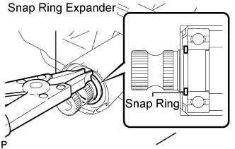
- NOTICE:
- Do not damage the steering main shaft.
| 10. REMOVE STEERING COLUMN TUBE ASSEMBLY LOWER |
Remove the steering column tube assembly lower from the steering column tube assembly upper.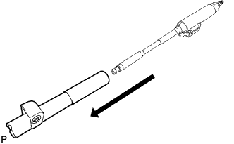
| 11. REMOVE TELESCOPIC STEERING GUIDE |
Remove the telescopic steering guide from the steering column tube assembly lower.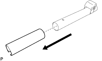
| 12. REMOVE STEERING COLUMN BRACKET SPACER |
Secure the steering column tube assembly lower in a vise.
Using SST and a hammer, remove the steering column bracket spacer from the steering column tube assembly lower.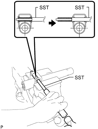
- SST
- 09201-10000
(09201-01080)
09950-70010 (09951-07100)
| 13. REMOVE TILT STEERING SUPPORT COLLAR |
Remove the 2 tilt steering support collars from the steering column tube assembly lower.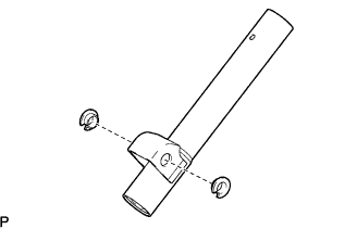
| 14. REMOVE STEERING MAIN SHAFT ASSEMBLY |
Secure the steering column tube assembly upper in a vise.
Using a snap ring expander, remove the steering main shaft snap ring from the steering main shaft.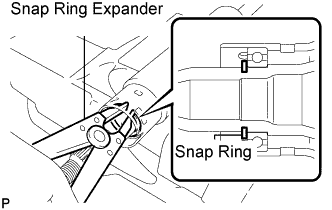
- NOTICE:
- Do not damage the steering main shaft.
Remove the steering main shaft from the steering column tube assembly upper.