REASSEMBLY
Removal / installation
- NOTICE:
- When using a vise, do not overtighten.
- When installing, coat the parts indicated by allows with MP grease (Click here).
- When using a vise, do not overtighten.
| 1. INSTALL STEERING MAIN SHAFT ASSEMBLY |

Secure the steering column tube assembly upper in a vise.
Install the steering main shaft assembly to the steering column tube assembly upper.
Using a snap ring expander, install a new steering main shaft snap ring to the steering main shaft.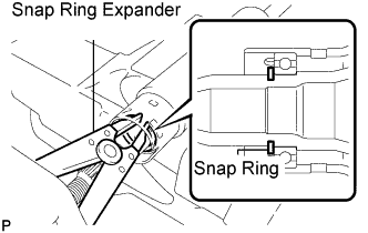

- NOTICE:
- Do not damage the steering main shaft.
- Securely install the steering main shaft snap ring to the groove on the steering main shaft.
- Do not damage the steering main shaft.
| 2. INSTALL TILT STEERING SUPPORT COLLAR |
Install the 2 tilt steering support collars to the steering column tube assembly lower.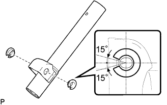
- NOTICE:
- Install the tilt steering support collars with the notches facing the direction shown in the illustration.
| 3. INSTALL STEERING COLUMN BRACKET SPACER |
Using a vise with an aluminum plate and a shop rag or a piece of cloth, install the steering column bracket spacer to the steering column tube assembly lower.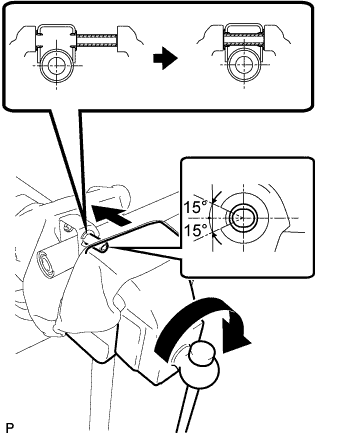
- NOTICE:
- Install the steering column bracket spacer with its bore facing the direction shown in the illustration.
| 4. INSTALL TELESCOPIC STEERING GUIDE |
Align the 3 protrusions on the telescopic steering guide with the 3 holes on the steering column tube assembly lower, and install the telescopic steering guide to the steering column tube assembly lower.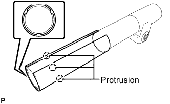
| 5. INSTALL STEERING COLUMN TUBE ASSEMBLY LOWER |
Apply MP grease to the area shown in the illustration on the steering main shaft assembly.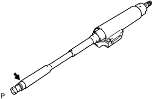
Install the steering column tube assembly lower to the steering column tube assembly upper.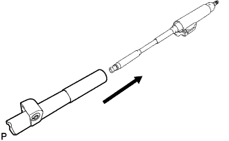
| 6. INSTALL STEERING MAIN SHAFT SNAP RING |
Secure the steering column tube assembly upper in a vise.
Using a snap ring expander, install a new steering main shaft snap ring to the steering main shaft.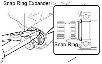
- NOTICE:
- Do not damage the steering main shaft.
- Securely install the steering main shaft snap ring to the groove on the steering main shaft.
- Do not damage the steering main shaft.
| 7. INSTALL TILT STEERING PAWL ASSEMBLY |
Install the tilt steering pawl to the steering column tube assembly upper.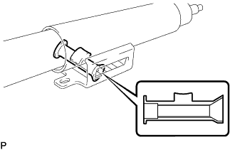
- NOTICE:
- Make sure that the tilt steering pawl is installed in the collect direction as shown in the illustration.
| 8. INSTALL BREAK AWAY BRACKET |
Apply MP grease to the sliding surface of the break away bracket, and install it to the steering column tube assembly upper.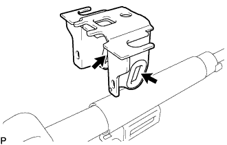
| 9. INSTALL STEERING COLUMN TUBE STOPPER |
Apply MP grease to the sliding surface of the steering column tube stopper (with groove).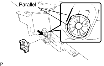
Install the steering column tube stopper (with groove) to the break away bracket as shown in the illustration.
Apply MP grease to the sliding surface of the steering column tube stopper (without groove).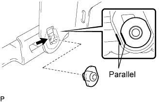
Install the steering column tube stopper (without groove) to the break away bracket as shown in the illustration.
| 10. INSTALL NO. 1 TILT LEVER LOCK BOLT |
Apply MP grease to the sliding surface of the steering telescopic lever, and insert the No. 1 tilt lever lock bolt to the steering telescopic lever.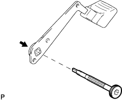
Install the No. 1 tilt lever lock bolt to the break away bracket.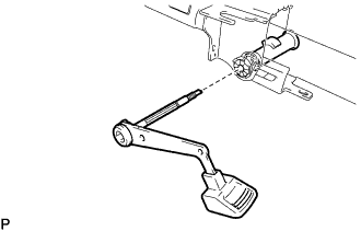
- NOTICE:
- Do not drop the steering column tube stopper.
- Securely insert the No. 1 tilt lever lock bolt into the hole of the tilt steering pawl.
- Do not drop the steering column tube stopper.
Apply MP grease to the sliding surface of the thrust needle roller bearing, and install it to the No. 1 tilt lever lock bolt.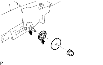
Install the tilt steering rotor.
Temporarily tighten a new tilt steering adjusting nut.
- NOTICE:
- The tilt steering adjusting nut is a left-hand threaded nut.
Using a socket hexagon wrench (8 mm), torque the No. 1 tilt lever lock bolt.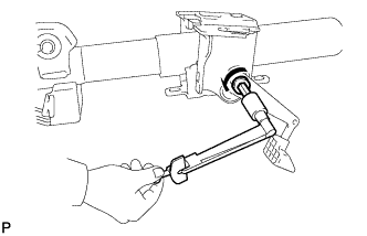
- Torque:
- 2.0 N*m{ 20 kgf*cm , 18 in.*lbf }
- NOTICE:
- The No. 1 tilt lever lock bolt is a left-hand threaded bolt.
| 11. INSTALL NO. 1 TILT STEERING SUPPORT REINFORCE |
Install the tilt steering support reinforce to the steering tilt lever with the No. 2 tilt lever lock bolt.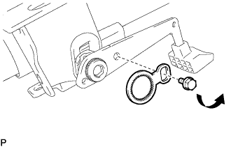
- Torque:
- 5.4 N*m{ 55 kgf*cm , 48 in.*lbf }
- NOTICE:
- The No. 2 tilt lever lock bolt is a left-hand threaded bolt.
| 12. INSTALL NO. 1 TILT STEERING ADJUSTING NUT |
Turn the steering tilt lever to the lock position.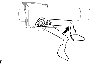
Using a socket hexagon wrench (8 mm), hold the No. 1 tilt lever lock bolt and tighten the tilt steering adjusting nut.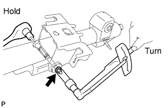
- Torque:
- 3.0 N*m{ 31 kgf*cm , 27 in.*lbf }
- NOTICE:
- The steering adjusting nut is a left-hand threaded nut.
Using pliers, stake the No. 1 tilt steering adjusting nut.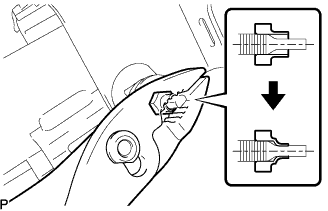
- NOTICE:
- After installation, make sure that the No. 1 tilt steering adjusting nut is securely staked.
| 13. INSTALL TILT STEERING JUMP UP SPRING |
Secure the break away bracket in a vise.
Using pliers, install the tilt jump up spring to the break away bracket as shown in the illustration.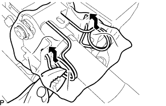
- HINT:
- Use a shop rag or a piece of cloth to prevent the spring from flying out.
| 14. INSTALL TILT LEVER RETURN SPRING |
Using SST, install the tilt lever return spring to the break away bracket and steering tilt lever.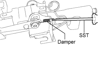
- SST
- 09921-00010
- NOTICE:
- Do not drop the damper from the tilt lever return spring.
- HINT:
- Use a shop rag or a piece of cloth to prevent the spring from flying out.
| 15. INSTALL BREAK AWAY COLLAR SUB-ASSEMBLY |
Install the 2 break away collar sub-assemblies and the 2 break away capsules to the break away bracket.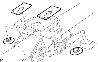
- NOTICE:
- Do not crush the disc springs of the break away collars.
| 16. INSTALL TILT STEERING SUPPORT |
Install the tilt steering support to the steering column tube assembly lower with the bolt.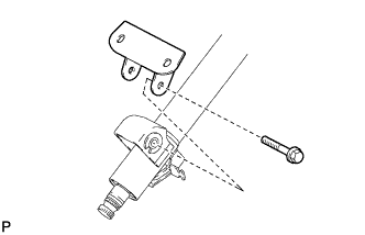
- Torque:
- 15 N*m{ 153 kgf*cm , 11 ft.*lbf }
| 17. INSTALL STEERING LOCK ACTUATOR ASSEMBLY |
Temporarily install the steering lock actuator assembly with 2 new tapered-head bolts.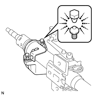
Tighten the 2 tapered-head bolts until the bolt heads break off.