ECM Communication Stop Mode
Circuit diagnosis
DESCRIPTION
| Detection Item |
Symptom |
Trouble Area |
| ECM Communication Stop Mode |
|
|
- HINT:
- "Engine" and "ECT" refer to the circuit that includes the ECM.
WIRING DIAGRAM
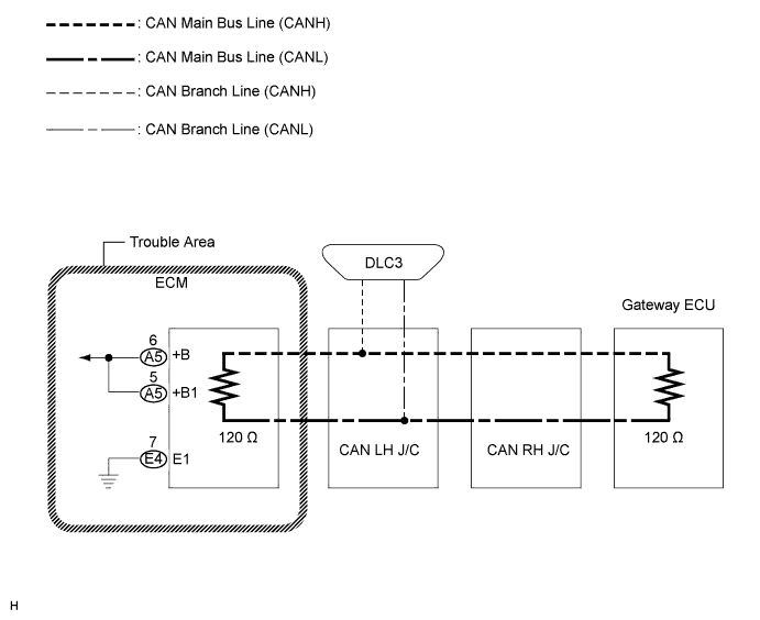

INSPECTION PROCEDURE
| 1. CHECK WIRE HARNESS (+B1, +B, E) |

Turn the engine switch off.
Disconnect the ECM connectors (E4) and (A5).
Measure the resistance according to the value(s) in the table below.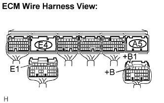
- Standard resistance:
Tester Connection
Condition
Specified Value
E4-7 (E1) - Body ground
Always
Below 1 Ω
Measure the voltage according to the value(s) in the table below.
- Standard voltage:
Tester Connection
Condition
Specified Value
A5-5 (+B1) - Body ground
Engine switch off
10 to 14 V
A5-6 (+B) - Body ground
Engine switch off
10 to 14 V
|
|
||||

| OK | ||
 |
||
| ||