Transmission Control Switch Circuit
Circuit diagnosis
DESCRIPTION
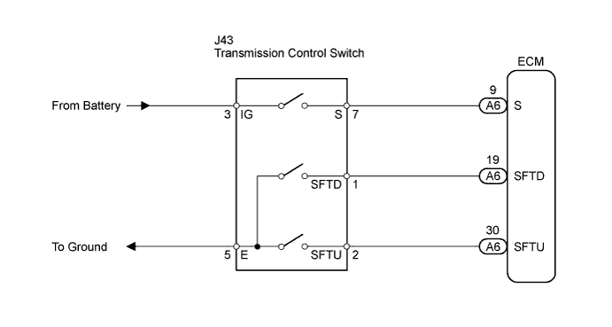
When moving the shift lever into the S position using the transmission control switch, it is possible to switch the shift range position between "1" (first range) and "6" (sixth range).Shifting up "+" once raises one shift range position, and shifting down "-" lowers one shift range position.
WIRING DIAGRAM

INSPECTION PROCEDURE
| 1. CHECK HARNESS AND CONNECTOR (BATTERY - TRANSMISSION CONTROL SWITCH) |

Disconnect the transmission control switch connector of shift lock control unit assembly.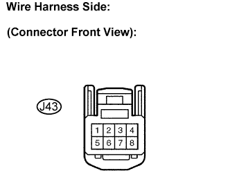
Measure the voltage according to the value(s) in the table below.
- Standard voltage:
Switch Condition
Tester Connection
Specified Condition
Engine switch on (IG)
3 - Body ground
10 to 14 V
Engine switch off
↑
Below 1 V
|
|
||||

| OK | |
 |
| 2. CHECK HARNESS AND CONNECTOR (TRANSMISSION CONTROL SWITCH - BODY GROUND) |
Measure the resistance according to the value(s) in the table below.
- Standard resistance:
Tester Connection
Specified Condition
5 - Body ground
Below 1 Ω
|
|
||||
| OK | |
|
| 3. INSPECT TRANSMISSION CONTROL SWITCH |
Measure resistance between each terminal of shift lock control unit assembly when the shift lever is moved to each position.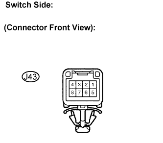
- Standard resistance:
Shift Position
Tester Connection
Specified Condition
S, "+" and "-"
3 - 7
Below 1 Ω
Except S, "+" and "-"
↑
10 kΩ or higher
Press continuously
"+"
(Up shift)
2 - 5
Below 1 Ω
S
↑
10 kΩ or higher
Press continuously
"-"
(Down shift)
1 - 5
Below 1 Ω
S
↑
10 kΩ or higher
|
|
||||
| OK | |
|
| 4. CHECK HARNESS AND CONNECTOR (TRANSMISSION CONTROL SWITCH - ECM) |
Connect the transmission control switch connector of shift lock control unit assembly.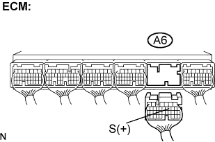
Disconnect the ECM connector.
Turn the ignition switch on (IG) position, and measure the voltage according to the value(s) in the table below when the shift lever is moved to each position.
- Standard voltage:
Shift Position
Tester Connection
Specified Condition
S, "+" and "-"
A6-9 (S) - Body ground
10 to 14 V
Except S, "+" and "-"
↑
Below 1 V
Turn the ignition switch off position.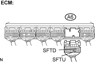
Disconnect the ECM connector.
Measure the resistance according to the value(s) in the table below when the shift lever is moved to each position.
- Standard resistance:
Shift Position
Tester Connection
Specified Condition
Press continuously
"+"
(Up shift)
A6-30 (SFTU) - Body ground
Below 1 Ω
S
↑
10 kΩ or higher
Press continuously
"-"
(Down shift)
A6-19 (SFTD) - Body ground
Below 1 Ω
S
↑
10 kΩ or higher
|
|
||||
| OK | ||
 |
||
| ||