INSTALLATION
Removal / installation
| 1. INSTALL FRONT STABILIZER BAR |

Install the front stabilizer bar to the vehicle.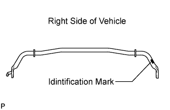

- NOTICE:
- The identification mark must be on the right side of the vehicle when installing the front stabilizer bar.
| 2. INSTALL FRONT NO. 1 STABILIZER BAR BUSHING |
Install the 2 front No. 1 stabilizer bar bushings as shown in the illustration.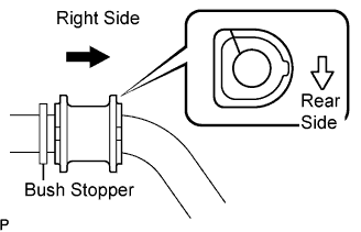
- NOTICE:
- Be sure to install the front No. 1 stabilizer bar bushings so that the cutouts face the front of the vehicle.
| 3. INSTALL FRONT NO. 1 STABILIZER BRACKET LH |
Press the front No. 1 stabilizer bracket LH against the frame toward the outside of the vehicle and temporarily tighten bolt A.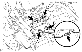
Install bolt B, fully tighten bolt A, and then install bolts C and D.
Install the skid control sensor wire clamp to the front No. 1 stabilizer bracket LH.
- Torque:
- 49 N*m{ 500 kgf*cm , 36 ft.*lbf }
| 4. INSTALL FRONT NO. 1 STABILIZER BRACKET RH |
- HINT:
- Install the RH side following the same procedures as for the LH side.
| 5. INSTALL FRONT NO. 2 STABILIZER BRACKET LH |
Install the front No. 2 stabilizer bracket LH on the vehicle with the 2 bolts.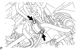
- Torque:
- 49 N*m{ 500 kgf*cm , 36 ft.*lbf }
| 6. INSTALL FRONT NO. 2 STABILIZER BRACKET RH |
- HINT:
- Install the RH side following the same procedure as for the LH side.
| 7. INSTALL FRONT STABILIZER LINK ASSEMBLY LH |
Install the front stabilizer link assembly LH with the 2 nuts.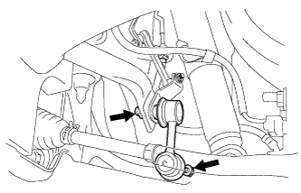
- Torque:
- 84 N*m{ 856 kgf*cm , 62 ft.*lbf }
- HINT:
- If the ball joint turns together with the nut, use a hexagon (6 mm) wrench to hold the stud.
| 8. INSTALL FRONT STABILIZER LINK ASSEMBLY RH |
- HINT:
- Install the RH side following the same procedure as for the LH side.
| 9. CONNECT FRONT HEIGHT CONTROL SENSOR LINK ASSEMBLY |
| 10. INSTALL REAR ENGINE UNDER COVER LH |
Install the engine under cover LH with the bolt.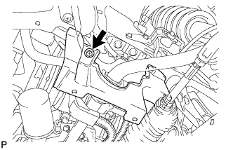
| 11. INSTALL REAR ENGINE UNDER COVER RH |
- HINT:
- Install the RH side following the same procedure as for the LH side.
| 12. INSTALL ENGINE UNDER COVER LH |
| 13. INSTALL FRONT WHEEL |
- Torque:
- 103 N*m{ 1,050 kgf*cm , 72 ft.*lbf }
| 14. INSPECT AND ADJUST FRONT WHEEL ALIGNMENT |