ADJUSTMENT
Removal / installation
| 1. INSPECT TIRES |

| 2. MEASURE VEHICLE HEIGHT |
Bounce the vehicle at the corners up and down to stabilize the suspension and inspect vehicle height.
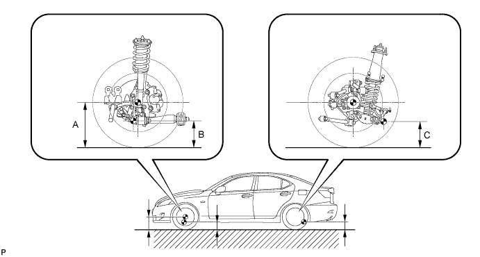

- Vehicle height:
Standard Suspension type
Wheel size
Front (A-B)
Rear (C)
normal
16 in. wheel
111 mm (4.37 in.)
212 mm (8.35 in.)
17 in. wheel
214 mm (8.43 in.)
18 in. wheel
220 mm (8.66 in.)
sports
18 in. wheel
121 mm (4.76 in.)
220 mm (8.66 in.)
- Measuring points:
- A:
- Ground clearance of front wheel center
- B:
- Ground clearance of front center position of front suspension lower arm assembly front bushing installation bolt head
- C:
- Ground clearance of rear center position of rear No. 2 suspension arm bushing installation bolt threads
- NOTICE:
- Before inspecting the wheel alignment, adjust the vehicle height to the specified value.
- Be sure to perform measurement on a level surface.
- If it is required to go under the vehicle for measurement, confirm that the parking brake is applied and the vehicle is secured with chocks.
- Before inspecting the wheel alignment, adjust the vehicle height to the specified value.
| 3. INSPECT TOE-IN |
Bounce the vehicle up and down at the corners to stabilize the suspension.
Release the parking brake and move the shift lever to the neutral position.
Push the vehicle straight ahead approximately 5 m (16.4 ft.).(*1)
Put tread center marks on the rearmost points of the front wheels and measure the distance between the marks (dimension B).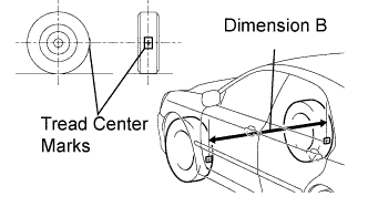
Slowly push the vehicle straight ahead to cause the front wheels to rotate 180° using a front tire pressure valve as a reference point.
- HINT:
- Do not allow the wheels to rotate more than 180°. If the wheels rotate more than 180°, perform the procedure from *1 again.
Measure the distance between the tread center marks on the front side of the wheels.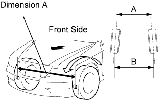
- Toe-in:
Toe-in (total)
A - B: 1.0 +- 2 mm (0.04 +- 0.08 in.)
- HINT:
- If toe-in is not within the specified range, adjust it at the rack ends.
| 4. ADJUST TOE-IN |
Measure the thread lengths of the right and left rack ends.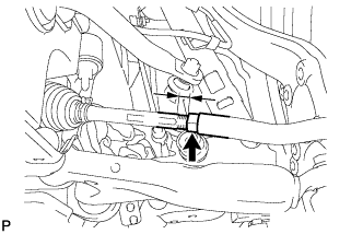
- Standard:
- Difference in thread length is 1.5 mm (0.059 in.) or less
Remove the rack boot set clips.
Loosen the tie rod end lock nuts.
Adjust the rack ends if the difference in thread length between the right and left rack ends is not within the specified range.
Extend the shorter rack end if the measured toe-in deviates toward the outer-side.
Shorten the longer rack end if the measured toe-in deviates toward the inner-side.
Turn the right and left rack ends by an equal amount to adjust toe-in.
- HINT:
- Try to adjust toe-in to the center of the specified range.
Make sure that the lengths of the right and left rack ends are the same.
Torque the tie rod end lock nuts.
- Torque:
- 56 N*m{ 571 kgf*cm , 41 ft.*lbf }
- NOTICE:
- Temporarily tighten the lock nut while holding the hexagonal part of the steering rack end so that the lock nut and the steering rack end do not turn together. Hold the width across flat of the tie rod end and tighten the lock nut.
Place the boots on the seats and install the clips.
- HINT:
- Make sure that the boots are not twisted.
| 5. INSPECT WHEEL ANGLE |
Put tread center marks on the rearmost points of the turning radius gauge.
Turn the steering wheel fully left and right and measure the turning angle.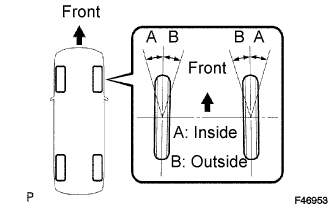
- Wheel turning angle:
Standard Suspension type
Inside wheel
Outside wheel (Reference)
normal
41°34'+- 2° (41.57°+-2°)
36°10' (36.17°)
sports
41°26'+- 2° (41.43°+-2°)
35°56' (35.93°)
| 6. INSPECT CAMBER, CASTER AND STEERING AXIS INCLINATION |
Place a front wheel on the center of the turning radius gauge.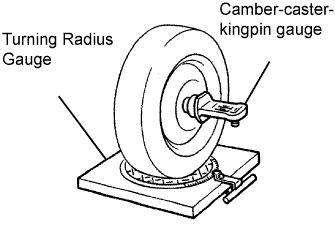
Remove the center ornament.
Install the camber-caster-kingpin gauge at the center of the axle hub or drive shaft.
Inspect the camber, caster, and steering axis inclination.
- Camber, caster, and steering axis inclination:
Standard Suspension Type
Wheel size
Camber angle
Caster angle
Steering axis inclination angle
Sports suspension
18 in. wheel
-0°36' +- 45'
(-0.6° +- 0.75°)
8°04' +- 45'
(8.07°+-0.75°)
10°55' +- 45'
(10.92°+-0.75°)
Normal suspension
16 in. wheel
-0°23'+- 45'
(-0.38°+-0.75°)
8°07' +- 45'
(8.12°+-0.75°)
10°41' +- 45'
(10.68°+-0.75°)
17 in. wheel
8°11'+- 45'
(8.18°+-0.75°)
18 in. wheel
8°04'+- 45'
(8.07°+-0.75°)
- NOTICE:
- Inspect while the vehicle is empty.
- The maximum tolerance of right and left difference for the camber and caster is 30' (0.5°) or less.
- Inspect while the vehicle is empty.
Remove the camber-caster-kingpin gauge.
Install the center ornament.
If the caster and steering axis inclination are not within the specified values after the camber has been correctly adjusted, recheck the suspension parts for damaged and/or worn out parts.
| 7. INSPECT FRONT SUSPENSION |
Inspect the front suspension member.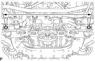
Measure the dimension between the center of the installation bolts of the front lower suspension arm.
- Standard:
- 692.5 to 699.5 mm (27.26 to 27.54 in.)
Inspect the front lower suspension arm assembly.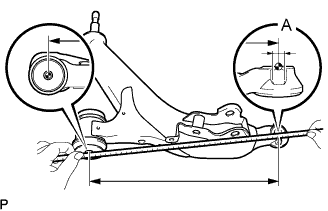
Remove the front lower suspension arm assembly. (Click here).
Measure the dimension between the center of the front lower suspension arm assembly bush and the center of position A.
- Standard:
- 362 to 364.6 mm (14.25 to 14.35 in.)
- HINT:
- If the dimension of the front lower suspension arm assembly changes 2 mm (0.079 in.), the camber will change approximately 15' (0.25°).
Inspect the front upper suspension arm assembly.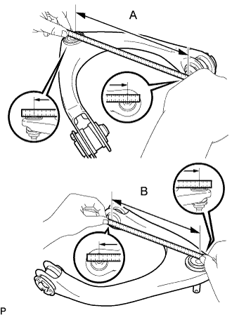
Remove the front upper suspension arm assembly. (Click here).
Measure the dimension between the center of the front upper suspension arm assembly bush and the center of the ball joint stud.
- Standard:
- A:
- 241 to 242.6 mm (9.49 to 9.55 in.)
- B:
- 215.1 to 216.7 mm (8.47 to 8.53 in.)
- HINT:
- If the dimension of the front upper suspension arm assembly changes 2 mm (0.079 in.), the camber will change approximately 15' (0.25°).