Cranking Holding Function Circuit
Circuit diagnosis
DESCRIPTION
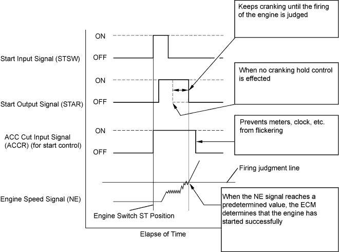
The cranking holding control system provides current to the starter when the ECM detects the engine switch's start signal (STSW). When the ECM performs a firing judgment, the system cuts current to the starter. When an ECM receives the STSW signal, it turns on the ST CUT relay, which prevents flickering of the combination meter, clock, audio system, etc. Also, the ECM sends a signal to the ECM's STAR terminal. Then the STAR output signal travels through the park/neutral position (PNP) switch to the STARTER relay, causing the starter to activate.When the engine is cranking, the starter operation signal is sent to the ECM's STA terminal.

WIRING DIAGRAM
Refer to DTC P0617 (Click here).INSPECTION PROCEDURE
| 1. CHECK CRANKING |

When turning the engine switch to the START position, check whether the starter motor starts.
|
|
||||

| NG | |
 |
| 2. READ VALUE OF INTELLIGENT TESTER (STA SIGNAL) |
Connect the intelligent tester to the DLC3.
Turn the engine switch on (IG) and turn the tester ON.
Enter the following menus: Power train / Engine / Data List / Starter Signal.
Check the result when the engine switch is turned to on (IG) and START.
- Standard:
Engine Switch Position
ON (IG)
START
STARTER SIG
OFF
ON
|
|
||||

| NG | |
|
| 3. INSPECT ECM (STAR AND STSW VOLTAGE) |
Measure the voltage of the A5 and E4 ECM connectors while cranking the engine.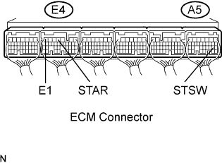
- Standard voltage:
Tester Connection
Specified Condition
STAR (E4-4) - E1 (E4-7)
9 to 14 V
STSW (A5-19) - E1 (E4-7)
9 to 14 V
- Result:
Terminal STAR
Terminal STSW
Proceed to
9 to 14 V
9 to 14 V
A
0 V
9 to 14 V
B
0 V
0 V
C
|
|
||||
|
|
||||
| A | |
|
| 4. INSPECT ST CUT RELAY |
Remove the ST CUT relay from the engine room J/B and R/B No. 2.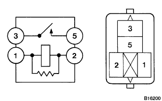
Measure the resistance of the ST CUT relay.
- Standard resistance:
Tester Connection
Specified Condition
3 - 5
10 kΩ or higher
3 - 5
Below 1 Ω
(when battery voltage applied to terminals 1 and 2)
|
|
||||
| OK | |
|
| 5. INSPECT PARK / NEUTRAL POSITION SWITCH (A/T) OR CLUTCH SWITCH ASSEMBLY (M/T) |
Disconnect the park/neutral position (PNP) switch (A/T) or clutch switch (M/T) connector.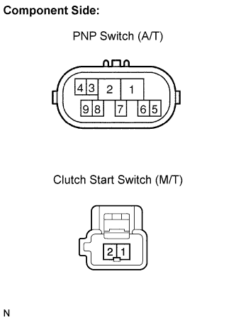
Measure the resistance between each terminal shown below when the shift lever is moved to each range.
- Standard resistance (A/T):
Shift Position
Tester Connection
Specified Condition
P
4 - 5
Below 1 Ω
N
4 - 5
Below 1 Ω
- Standard resistance (M/T):
Clutch Pedal Operation
Tester Connection
Specified Condition
Depressed
1 - 2
Below 1 Ω
|
|
||||
| OK | ||
 |
||
| ||
| 6. INSPECT STARTER RELAY |
Remove the starter relay from the engine room J/B and R/B No. 1.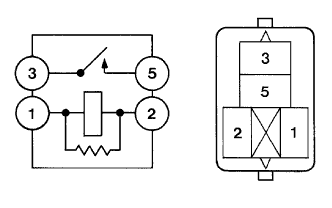
Measure the resistance of the starter relay.
- Standard resistance:
Tester Connection
Specified Condition
3 - 5
10 kΩ or higher
3 - 5
Below 1 Ω
(when battery voltage applied to terminals 1 and 2)
|
|
||||
| OK | |
|
| 7. CHECK HARNESS AND CONNECTOR (PARK/NEUTRAL POSITION SWITCH - STARTER RELAY) |
Check the harness and the connectors between the park/neutral position switch and the starter relay.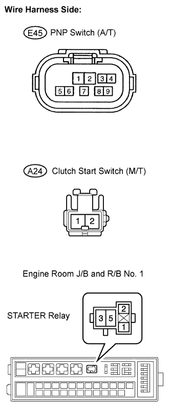
Disconnect the E45*1, A24*2 switch connector.*1: A/T*2: M/T
Remove the starter relay from the engine room J/B and R/B No. 1.
Measure the resistance of the wire harness side connectors.
- Standard resistance (A/T) (Check for open):
Tester Connection
Specified Condition
Park/Neutral position switch (E45-5) - Starter relay (1)
Below 1 Ω
- Standard resistance (M/T) (Check for open):
Tester Connection
Specified Condition
Clutch start switch (A24-2) - Starter relay (1)
Below 1 Ω
- Standard resistance (A/T) (Check for short):
Tester Connection
Specified Condition
Park/Neutral position switch (E45-5) or Starter relay (1) - Body ground
10 kΩ or higher
- Standard resistance (M/T) (Check for short):
Tester Connection
Specified Condition
Clutch start switch (A24-2) or Starter relay (1) - Body ground
10 kΩ or higher
Check the harness and the connector between the starter relay and the body ground.
Remove the starter relay from the engine room J/B and R/B No. 1.
Measure the resistance of the starter relay and the body ground.
- Standard resistance (Check for open):
Tester Connection
Specified Condition
Starter relay (2) - Body ground
Below 1 Ω
|
|
||||
| OK | |
|
| 8. INSPECT ENGINE ROOM RELAY BLOCK (STARTER RELAY VOLTAGE) |
Remove the starter relay from the engine room J/B and R/B No. 1.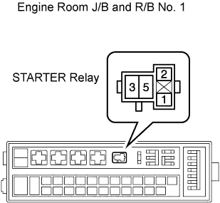
Measure the voltage of the engine room J/B and R/B No. 1 and the body ground.
- Standard voltage:
Tester Connection
Specified Condition
Starter relay (5) - Body ground
9 to 14 V
|
|
||||
| OK | |
|
| 9. INSPECT STARTER ASSEMBLY |
|
|
||||
| OK | ||
|
||
| ||
| 10. CHECK HARNESS AND CONNECTOR (POWER SOURCE CONTROL ECU - ECM) |
Check the harness and the connectors between the power source control ECU and ECM.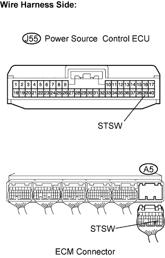
Disconnect the power source control ECU connector.
Disconnect the A5 ECM connector.
Measure the resistance of the wire harness side connectors.
- Standard resistance (Check for open):
Tester Connection
Specified Condition
J55-39 (STSW) - A5-19 (STSW)
Below 1 Ω
- Standard resistance (Check for short):
Tester Connection
Specified Condition
J55-39 (STSW) or A5-19 (STSW) - Body ground
10 kΩ or higher
|
|
||||
| OK | ||
|
||
| ||