Fuel Pump Control Circuit
Circuit diagnosis
DESCRIPTION
Refer to DTC P0230 (Click here).WIRING DIAGRAM
Refer to DTC P0230 (Click here).INSPECTION PROCEDURE
| 1. CHECK FUEL PUMP (FUEL PUMP OPERATION) |

Check if there is pressure in the fuel inlet hose.
- HINT:
- If there is fuel pressure, you will hear the sound of fuel flowing.
|
|
||||

| NG | |
 |
| 2. PERFORM ACTIVE TEST BY INTELLIGENT TESTER (OPERATE CIRCUIT OPENING RELAY) |
Connect the intelligent tester to the DLC3.
Turn the engine switch on (IG) and turn the intelligent tester ON.
Enter the following menus: Power train / Engine / Active Test / Control the Fuel Pump / Speed.
Check the operation of the relay while operating it using the intelligent tester.
- OK:
- Operating noise can be heard from the relay.
|
|
||||
| NG | |
|
| 3. INSPECT ECM POWER SOURCE CIRCUIT |
|
|
||||

| OK | |
|
| 4. INSPECT FUSE (F/PMP FUSE) |
Remove the F/PMP fuse from the engine room J/B and R/B No. 2.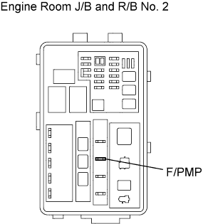

Measure the resistance of the F/PMP fuse.
- Standard resistance:
- Below 1 Ω
|
|
||||
| OK | |
|
| 5. INSPECT INTEGRATION RELAY (EFI NO. 2 RELAY) |
Remove the integration relay from the engine room J/B and R/B No. 2.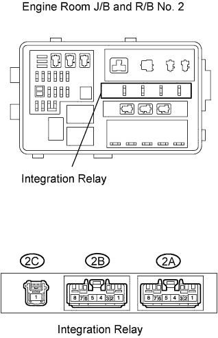
Measure the resistance of the EFI No. 2 relay.
- Standard resistance:
Tester Connection
Specified Condition
2B-4 - 2C-1
10 kΩ or higher
2B-4 - 2C-1
Below 1 Ω
(when battery voltage applied to terminals 2B-3 and 2B-2)
|
|
||||
| OK | |
|
| 6. INSPECT INTEGRATION RELAY (C/OPN RELAY) |
Remove the integration relay from the engine room J/B and R/B No. 2.
Measure the resistance of the C/OPN relay.
- Standard resistance:
Tester Connection
Specified Condition
2B-6 - 2B-8
10 kΩ or higher
2B-6 - 2B-8
Below 1 Ω
(when battery voltage applied to terminals 2B-6 and 2B-7)
|
|
||||
| OK | |
|
| 7. INSPECT ECM (FC VOLTAGE) |
Turn the engine switch on (IG).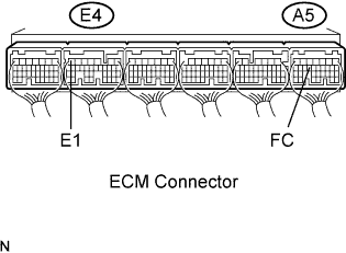
Measure the voltage of the A5 and E4 ECM connectors.
- Standard voltage:
Tester Connection
Specified Condition
FC (A5-14) - E1 (E4-7)
9 to 14 V
|
|
||||
| NG | ||
 |
||
| ||
| 8. INSPECT F/PMP RELAY |
Remove the F/PMP relay from the engine room J/B and R/B No. 2.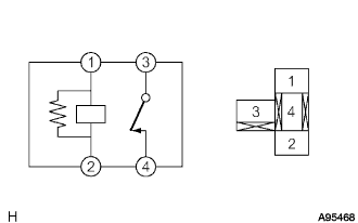
Measure the resistance of the F/PMP relay.
- Standard resistance:
Tester Connection
Specified Condition
3 - 4
10 kΩ or higher
3 - 4
Below 1 Ω
(when battery voltage applied to terminals 1 and 2)
|
|
||||
| OK | |
|
| 9. INSPECT FUEL PUMP |
Inspect fuel pump resistance.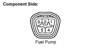
Measure the resistance between terminals 4 and 5.
- Standard resistance:
- 0.2 to 3.0 Ω at 20°C (68°F)
Inspect fuel pump operation.
Apply battery voltage to both the terminals. Check that the pump operates.
- NOTICE:
- These tests must be done quickly (within 10 seconds) to prevent the coil from burning out.
- Keep fuel pump as far away from the battery as possible.
- Always switch at the battery side.
- These tests must be done quickly (within 10 seconds) to prevent the coil from burning out.
|
|
||||
| OK | |
|
| 10. CHECK HARNESS AND CONNECTOR (FUEL PUMP - F/PMP RELAY) |
Check the harness and the connectors between the fuel pump and the F/PMP relay.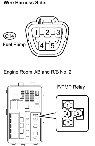
Disconnect the fuel pump connector.
Remove the F/PMP relay from the engine room J/B and R/B No. 2.
Measure the resistance of the wire harness side connectors.
- Standard resistance (Check for open):
Tester Connection
Specified Condition
Fuel pump (Q14-4) - F/PMP relay (4)
Below 1 Ω
- Standard resistance (Check for short):
Tester Connection
Specified Condition
Fuel pump (Q14-4) or F/PMP (4) - Body ground
10 kΩ or higher
Check the harness and the connectors between the fuel pump and the body ground.
Disconnect the fuel pump connector.
Measure the resistance of the wire harness side connector and the body ground.
- Standard resistance (Check for open):
Tester Connection
Specified Condition
Fuel pump (Q14-5) - Body ground
10 kΩ or higher
|
|
||||
| OK | |
|
| 11. CHECK HARNESS AND CONNECTOR (INTEGRATION RELAY - F/PMP RELAY) |
Remove the integration relay from the engine room J/B and R/B No. 2.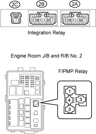
Remove the F/PMP relay from the engine room J/B and R/B No. 2.
Measure the resistance of the wire harness side connectors.
- Standard resistance (Check for open):
Tester Connection
Specified Condition
Integration relay (2B-8) - F/PMP relay (1)
Below 1 Ω
Integration relay (2B-8) - F/PMP relay (3)
Below 1 Ω
- Standard resistance (Check for short):
Tester Connection
Specified Condition
Circuit opening relay (2B-8) or F/PMP relay (1) - Body ground
10 kΩ or higher
Circuit opening relay (2B-8) or F/PMP relay (3) - Body ground
10 kΩ or higher
|
|
||||
| OK | ||
|
||
| ||
| 12. INSPECT F/PMP RELAY |
Remove the F/PMP relay from the engine room J/B and R/B No. 2.
Measure the resistance of the F/PMP relay.
- Standard resistance:
Tester Connection
Specified Condition
3 - 4
10 kΩ or higher
3 - 4
Below 1 Ω
(when battery voltage applied to terminals 1 and 2)
|
|
||||
| OK | |
|
| 13. INSPECT FUEL PUMP RESISTER |
Measure the resistance of the fuel pump resistor.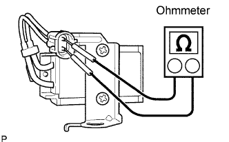
- Standard resistance:
- 0.30 to 0.34 Ω at 20°C (68°F)
|
|
||||
| OK | |
|
| 14. CHECK HARNESS AND CONNECTOR (F/PMP RELAY - FUEL PUMP RESISTER) |
Check the harness and the connectors between the F/PMP relay and the fuel pump resistor.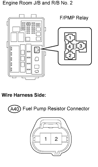
Remove the F/PMP relay from the engine room J/B and R/B No. 2.
Disconnect the fuel pump resistor connector.
Measure the resistance of the wire harness side connectors.
- Standard resistance (Check for open):
Tester Connection
Specified Condition
F/PMP relay (4) - Fuel pump resistor (A40-2)
Below 1 Ω
F/PMP relay (3) - Fuel pump resistor (A40-1)
Below 1 Ω
- Standard resistance (Check for short):
Tester Connection
Specified Condition
Fuel pump relay (4) or Fuel pump resistor (A40-2) - Body ground
10 kΩ or higher
Fuel pump relay (4) or Fuel pump resistor (A40-1) - Body ground
10 kΩ or higher
|
|
||||
| NG | ||
|
||
| ||