B1205
Diagnostic trouble codes
DESCRIPTION
- This DTC is detected when communication between the AFS ECU and the gateway ECU stops for more than 10 seconds.
| DTC No. |
DTC Detection Condition |
Trouble Area |
| B1205 |
AFS ECU communication stops |
|
WIRING DIAGRAM
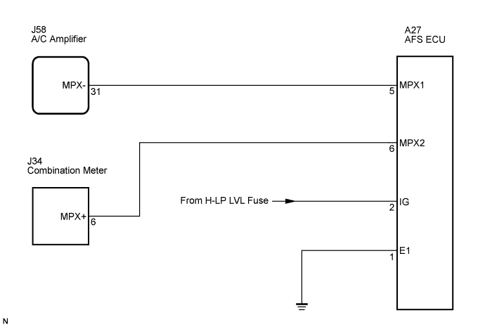

INSPECTION PROCEDURE
- HINT:
- When "+B of GND short malfunction of communication bus" DTCs (B1266 and B1267) are detected at the same time as "communication stop" DTC B1205, repair the "+B or GND short malfunction of communication bus" DTCs first.
| 1. INSPECT FUSE (H-LP LVL) |

Remove the H-LP LVL fuse from the main body ECU LH (cowl side J/B LH).
Measure the resistance of the fuse.
- Standard resistance:
- Below 1 Ω
|
|
||||

| OK | |
 |
| 2. CHECK WIRE HARNESS (AFS ECU - BATTERY AND BODY GROUND) |
Disconnect the A27 ECU connector.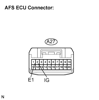
Turn the engine switch on (IG).
Measure the voltage and resistance of the wire harness side connector.
- Standard voltage:
Tester Connection
Condition
Specified Condition
IG (A27-2) - Body ground
Engine switch on (IG)
10 to 14 V
- Standard resistance:
Tester Connection
Specified Condition
E1 (A27-1) - Body ground
Below 1 Ω
|
|
||||
| OK | |
|
| 3. CHECK RESISTANCE OF COMMUNICATION LINE |
Disconnect the A27, J58 and J34 ECU connectors.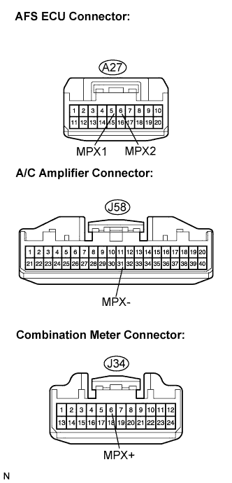
Measure the resistance between the specified terminals on the wire harness side connectors.
- Standard resistance:
Tester Connection
Specified Condition
MPX1 (A27-5) - MPX- (J58-31)
Below 1 Ω
MPX2 (A27-6) - MPX+ (J34-6)
Below 1 Ω
- Result:
Result
Proceed to
Both are OK
A
One is OK
B
Both are NG
C
|
|
||||
|
|
||||
| A | ||
 |
||
| ||