Rear Sunshade does not Operate with Rear Sunshade Switch
Circuit diagnosis
SYSTEM DESCRIPTION
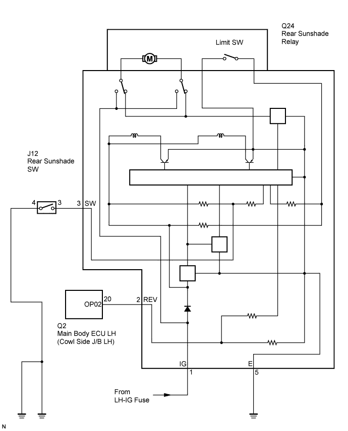
When the rear sunshade switch is pressed, a signal is sent directly to the rear sunshade relay.WIRING DIAGRAM

INSPECTION PROCEDURE
| 1. INSPECT FUSE (LH-IG) |

Remove the LH-IG fuse from the cowl side junction block LH.
Measure the resistance of the fuses.
- Standard resistance:
- Below 1 Ω
|
|
||||

| OK | |
 |
| 2. CHECK WIRE HARNESS (COWL SIDE JUNCTION BLOCK LH - RELAY, BATTERY AND BODY GROUND) |
Disconnect the Q24 relay connector.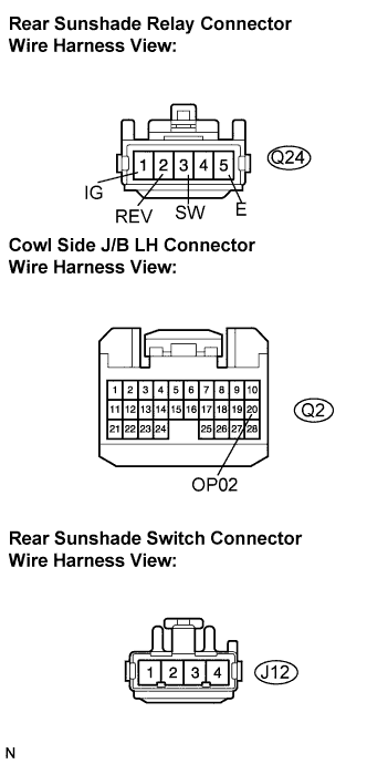
Disconnect the Q2 cowl side junction block LH connector.
Disconnect the J12 rear sunshade switch connector.
Measure the resistance of the wire harness side connectors.
- Standard resistance:
Tester Connection
Specified Condition
REV (Q24-2) - OP02 (Q2-20)
Below 1 Ω
SW (Q24-3) - J12-3
Below 1 Ω
E (Q24-5) - Body ground
Below 1 Ω
REV (Q24-2) - E (Q24-5)
10 kΩ or higher
SW (Q24-3) - E (Q24-5)
10 kΩ or higher
Turn the engine switch on (IG).
Measure the voltage of the wire harness side connector.
- Standard voltage:
Tester Connection
Specified Condition
IG (Q24-1) - Body ground
10 to 14 V
|
|
||||
| OK | |
|
| 3. INSPECT REAR SUNSHADE SWITCH |
Disconnect the connector from the rear sunshade switch.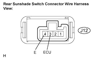
Measure the resistance between the terminals according to the value(s) in the table below.
- Standard resistance:
Tester connection
Condition
Specified condition
J12-3 (ECU) - J12-4 (E)
Rear sunshade switch is pressed
Below 1 Ω
J12-3 (ECU) - J12-4 (E)
Rear sunshade switch is not pressed
10 kΩ or higher
|
|
||||
| OK | ||
 |
||
| ||