Rear Sunshade Shift-linked Function does not Operate when Shift Lever is Moved to R Position
Circuit diagnosis
SYSTEM DESCRIPTION
When the engine switch is on (IG) and the rear sunshade is raised, moving the shift lever to R causes the Park/Neutral Position switch (A/T) or back-up light switch (M/T) to send a reverse-linked signal to the main body ECU LH. Then the main body ECU LH sends the signal through the multiplex communication line to the rear sunshade relay. The relay then lowers the rear sunshade.WIRING DIAGRAM
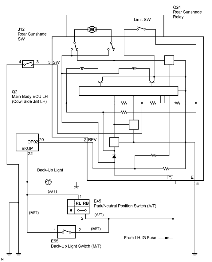

INSPECTION PROCEDURE
| 1. CHECK OPERATION |

Check that the back-up light comes on when the shift lever is moved to the R position.
- OK:
- Back-up light comes on when shift lever is moved to R position.
|
|
||||

| OK | |
 |
| 2. CHECK REAR SUNSHADE RELAY |
Disconnect the Q24 rear sunshade relay connector.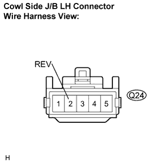
Measure the voltage of the wire harness side connectors.
- Standard voltage:
Tester connection
Condition
Specified condition
REV (Q24-2) - Body ground
Engine switch on (IG), shift lever on except R
Below 1 V
REV (Q24-2) - Body ground
Engine switch on (IG), shift lever on R
10 to 14 V
|
|
||||

| OK | ||
 |
||
| ||
| 3. CHECK WIRE HARNESS (MAIN BODY ECU LH - BACK-UP LIGHT SWITCH OR PNP SWITCH) |
Disconnect the Q2 cowl side junction block LH connector.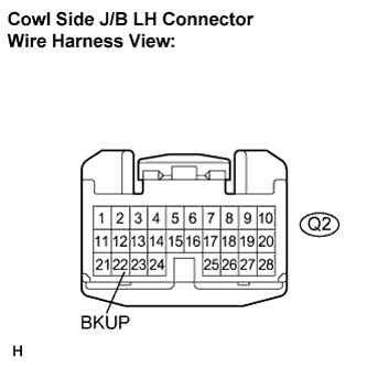
Measure the voltage of the wire harness side connectors.
- Standard voltage:
Tester connection
Condition
Specified condition
BKUP (Q2-22) - Body ground
Engine switch on (IG), shift lever on except R
Below 1 V
BKUP (Q2-22) - Body ground
Engine switch on (IG), shift lever on R
10 to 14 V
|
|
||||
| OK | |
|
| 4. CHECK WIRE HARNESS (REAR SUNSHADE RELAY - MAIN BODT ECU LH) |
Disconnect the Q24 relay connector.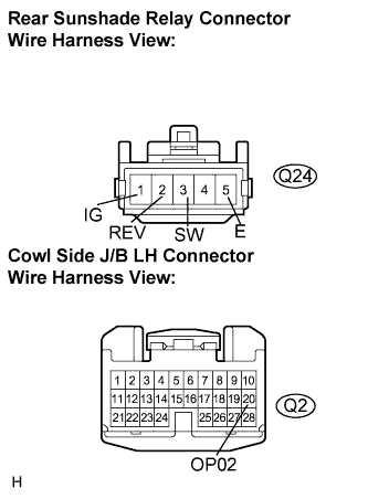
Disconnect the Q2 main body ECU LH connector.
Measure the resistance of the wire harness side connectors.
- Standard resistance:
Tester connection
Condition
Specified condition
REV (Q24-2) - OP02 (Q2-20)
Always
Below 1 Ω
|
|
||||
| OK | ||
|
||
| ||