ADJUSTMENT
Removal / installation
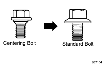

- HINT:
- Centering bolts are used to mount the hood hinge and hood lock. The hood and hood lock cannot be adjusted with the centering bolts on. Substitute the centering bolts with standard bolts (with washers) when making adjustments.
- A bolt without a torque specification is shown in the standard bolt chart (Click here).
- Centering bolts are used to mount the hood hinge and hood lock. The hood and hood lock cannot be adjusted with the centering bolts on. Substitute the centering bolts with standard bolts (with washers) when making adjustments.
| 1. REMOVE COOL AIR INTAKE DUCT SEAL |

Remove the 11 clips and intake duct seal.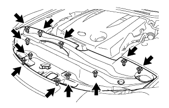
| 2. REMOVE FRONT BUMPER ASSEMBLY |
Using a screwdriver, turn the pin 90 degrees and remove the 2 pin hold clips.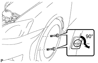
- HINT:
- Tape the screwdriver tip before use.
- Use the same procedures for the RH side and LH side.
- Tape the screwdriver tip before use.
Put protective tape around the front bumper assembly.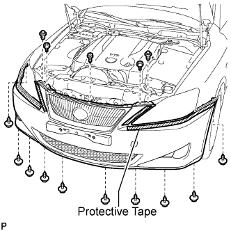
Using a clip remover, remove the 2 clips
Remove the 2 radiator grille protectors.
Remove the bolt and 10 screws.
Disengage the 5 claws and disconnect the front bumper assembly as shown in the illustration.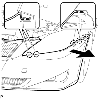
- HINT:
- Use the same procedures for the RH side and LH side.
Disconnect the headlight washer hose. (w/ headlight cleaner system)
Disconnect the connector and remove the front bumper assembly.
| 3. REMOVE MILLIMETER WAVE RADAR SENSOR ASSEMBLY (w/ Dynamic Radar Cruise Control System) |
Disconnect the connector.
Remove the 3 bolts and the millimeter wave radar sensor assembly.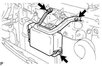
| 4. ADJUST HOOD SUB-ASSEMBLY |
Horizontally and vertically adjust the hood.
Disengage the 2 clamps and claw, and remove the hood hinge cover LH.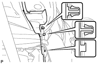
Disengage the 2 clamps, and remove the hood hinge cover RH.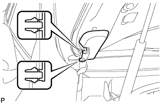
Loosen the hood's 4 hinge bolts.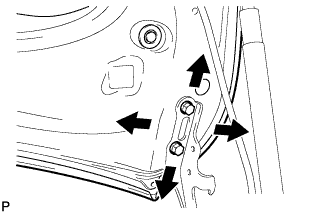
Move the hood and adjust the clearance between the hood and front fender.
Tighten the hood's 4 hinge bolts after the adjustment.
- Torque:
- 13 N*m{ 133 kgf*cm , 10 ft.*lbf }
Adjust the height of the hood front end using the cushion rubber.
Adjust the cushion rubber so that the height of the hood and fender are aligned.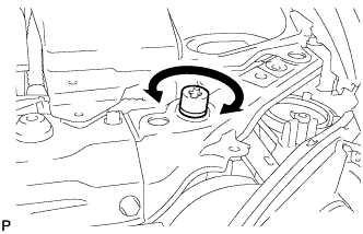
- HINT:
- Raise or lower the hood's front end by turning the cushion rubber.
Adjust the hood lock.
Using a screwdriver, remove the hood lock nut cap as shown in the illustration.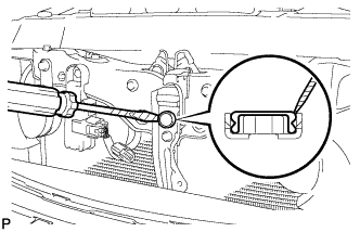
- HINT:
- Tape the screwdriver tip before use.
Loosen the 2 bolts and hood lock nut.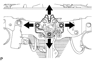
Tighten the bolts and nut after the adjustment.
- Torque:
- 8.0 N*m{ 82 kgf*cm , 71 in.*lbf }
Adjust the hood lock position so that the striker can enter it smoothly.
Install a new cap.
| 5. INSTALL MILLIMETER WAVE RADAR SENSOR ASSEMBLY (w/ Dynamic Radar Cruise Control System) |
|
|
Install the millimeter wave radar sensor with the 3 bolts.
- Torque:
- 5.5 N*m{ 56 kgf*cm , 49 in.*lbf }
Connect the connector.
| 6. INSTALL FRONT BUMPER ASSEMBLY |
| 7. INSTALL COOL AIR INTAKE DUCT SEAL |
Install the intake duct seal with the 11 clips.
| 8. ADJUST MILLIMETER WAVE RADAR SENSOR ASSEMBLY (w/ Dynamic Radar Cruise Control System) |
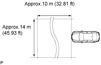 |
- CAUTION:
- Exposure to radio frequency emissions is hazardous to your health. It is hazardous to your health to be within 20 cm (7.9 in.) of the device's radio frequency aperture.
- NOTICE:
- This device complies with FCC radio frequency emission regulations.
- Perform measurements on a level surface.
- Make sure that no large pieces of metal are within a 10 m (32.81 ft) x 14 m (45.93 ft) area in front of the vehicle. If possible, the surrounding area should also be free of large metal objects.
- This device complies with FCC radio frequency emission regulations.
Before adjusting the radar beam axis, prepare the vehicle as follows:
Check the tire pressure and adjust it if necessary.
Remove all excess weight from the vehicle (luggage, heavy objects, etc. ).
Check and adjust the vertical direction of the radar sensor.
Remove dust, oil, and foreign matter from the radar sensor's level rack.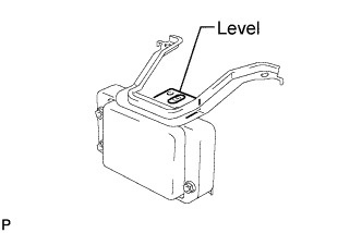
Set a level on the radar sensor's level rack.
Check that the air bubble is within the red frame on the level.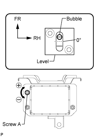
- OK:
- The air bubble is within the red frame on the level.
If the bubble is not within the red frame, use a hexagon wrench to adjust screw A until the air bubble is within the red frame.
- HINT:
- The adjustable range within the red frame on the level is + - 0.2°.
- The target angle is +0.2° (upward angle of 0.2°).
- The adjustable range within the red frame on the level is + - 0.2°.
- Result:
Adjustment Direction
Adjustment Procedure
Adjustment Angle
Vertical adjustment
- Upward direction: Turn screw A to negative (-) side
- Downward direction: Turn screw A to positive (+) side
Approx. 1.0° per turn
- Upward direction: Turn screw A to negative (-) side
Adjust the reflector height.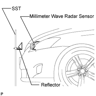
Adjust the reflector so that the center of the SST reflector is the same height as the millimeter wave radar sensor.
- SST
- 09870-60000
(09870-60010, 09870-60040)
- HINT:
- Prepare a 10 m (32.81 ft) string, a string with a sharp-pointed weight (plumb bob), and a 5 m (16.41 ft) tape measure.
Place the reflector.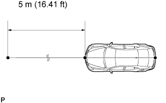
Hang the string (with weight) from the center of the vehicle's rear emblem. Mark the vehicle's rear center point on the ground. Repeat the same procedure for the front of the vehicle.
Set one end of the 10 m (32.82 ft) string on the vehicle's rear center point. Run the string over the vehicle's front center point to a position 5 m (16.41 ft) beyond the vehicle front center point, as shown in the illustration. Mark the 5 m (16.41 ft) position.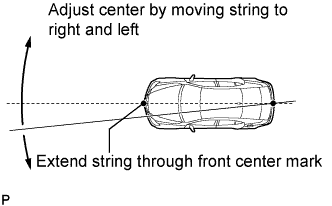
Using a tape measure, measure 12 mm (0.47 in.) to the left of the 5 m (16.41 ft) position. Place the reflector at that position.
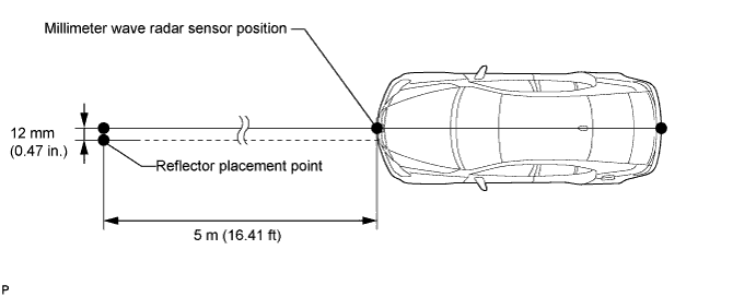
- NOTICE:
- Perform the operation as precisely as possible.
Adjust the radar beam axis.
Connect the intelligent tester to the DLC3.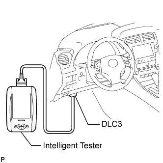
Turn the engine switch on (IG).
Turn the intelligent tester main switch on, and turn the cruise control main switch on.
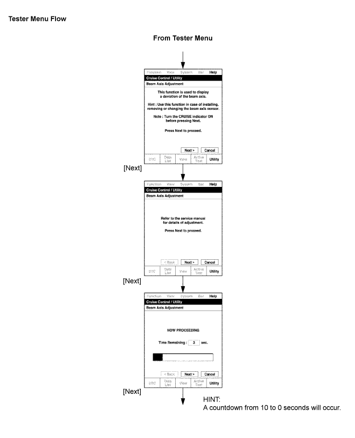
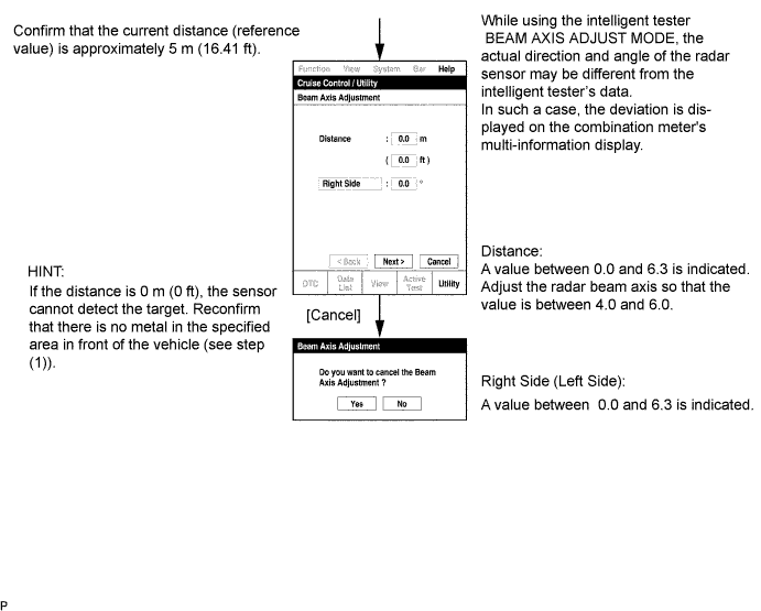
Check and adjust the horizontal direction of the radar sensor.
Check that the divergence of the radar beam axis is 0° .
- Standard:
- 0° (Both right and left)
- If the axis is not as specified, use a hexagon wrench to adjust screw B until the divergence of the radar beam axis is 0°.
Based on the measured divergence of the beam axis, turn and adjust screw B for horizontal adjustment of the millimeter wave radar sensor using a hexagon wrench.
- Result:
Adjustment Direction
Adjustment Procedure
Adjustment Angle
Horizontal adjustment
- Right direction: Turn screw B to positive (+) side.
- Left direction: Turn screw B to negative (-) side.
Approx. 0.33° per turn
- Right direction: Turn screw B to positive (+) side.
- HINT:
- If "LEFT SIDE: 1.0°" is displayed, the divergence is 1.0° in the left direction. Turn screw B approximately 3 turns to the negative (-) side.
- If the value does not change to 0°, it is possible that the sensor is aiming at something different. Reconfirm that there are no reflective materials in the surrounding area.
- If "LEFT SIDE: 1.0°" is displayed, the divergence is 1.0° in the left direction. Turn screw B approximately 3 turns to the negative (-) side.
Reset the radar sensor's driving learning values. Prepare a type of metal that can block radio waves, such as aluminum foil. Cover the radar sensor's left half with the aluminum foil for 10 seconds.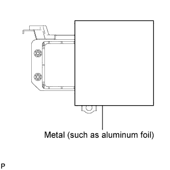
- NOTICE:
- Be sure to keep the reflector in place and make sure that there is nothing between the sensor's left half and the reflector.
- HINT:
- When the reset is completed, the buzzer sounds for 10 seconds.
Disconnect the intelligent tester from the DLC3.
Recheck and readjust the vertical direction of the radar sensor.
Set a level on the radar sensor's level rack.
Check that the air bubble is within the red frame on the level.
- OK:
- The air bubble is within the red frame on the level.
- If the bubble is not within the red frame, use a hexagon wrench to adjust screw A until the air bubble is within the red frame.
- HINT:
- The adjustable range within the red frame on the level is + -0.2°.
- The target angle is +0.2° (upward angle of 0.2°).
- The adjustable range within the red frame on the level is + -0.2°.
- Result:
Adjustment Direction
Adjustment Procedure
Adjustment Angle
Vertical adjustment
- Upward direction: Turn screw A to negative (-) side
- Downward direction: Turn screw A to positive (+) side
Approx. 1.0°per turn
- Upward direction: Turn screw A to negative (-) side
| 9. VEHICLE PREPARATION FOR FOG LIGHT AIM |
Prepare the vehicle:
- Ensure there is no damage or deformation to the body around the fog lights.
- Fill the fuel tank.
- Make sure that the oil is filled to the specified level.
- Make sure that the coolant is filled to the specified level.
- Inflate the tires to the appropriate pressure.
- Place the spare tire, tools, and jack in their original positions.
- Unload the trunk.
- Sit a person of average weight (75 kg, 165 lb) in the driver's seat.
- Ensure there is no damage or deformation to the body around the fog lights.
| 10. PREPARATION FOR FOG LIGHT AIMING |
Prepare the vehicle according to the following conditions: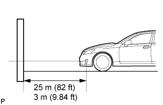
- Place the vehicle in a location that is dark enough to clearly observe the cutoff line. The cutoff line is a distinct line, below which light from the fog lights can be observed and above which it cannot.
- Place the vehicle at a 90° angle to the wall.
- Create a 25m (82 ft) distance between the vehicle (fog light bulb center) and the wall.
- Place the vehicle on a level surface.
- Bounce the vehicle up and down to settle the suspension.
- NOTICE:
- A distance of 25 m (82 ft) between the vehicle (fog light bulb center) and the wall is necessary for proper aim adjustment. If unavailable, secure a distance of exactly 3 m (9.84 ft) for check and adjustment. (The target zone will change with the distance, so follow the instructions in the illustration.)
- Place the vehicle in a location that is dark enough to clearly observe the cutoff line. The cutoff line is a distinct line, below which light from the fog lights can be observed and above which it cannot.
Prepare a piece of thick white paper (approximately 2 m (6.6 ft) (height) x 4 m (13.1 ft) (width)) to use as a screen.
Draw a vertical line down the center of screen (V line).
Set the screen as shown in the illustration.
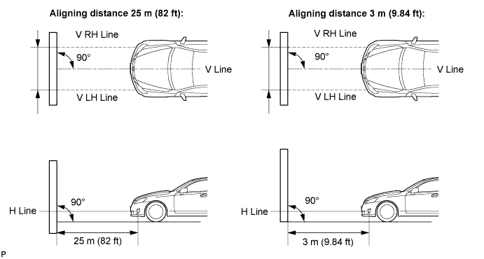
- HINT:
- Stand the screen perpendicular to the ground.
- Align the V line on the screen with the center of the vehicle.
- Stand the screen perpendicular to the ground.
Draw base lines (H line, V LH, V RH lines) on the screen as shown in the illustration.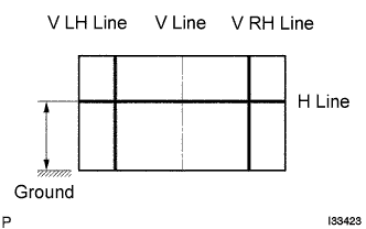
- HINT:
- Mark the fog light bulb center marks on the screen. If the center mark cannot be observed on the fog light, use the center of the fog light bulb or the manufacturer's name marked on the fog light as the center mark.
H Line (Fog light height):
Draw a horizontal line across the screen so that it passes through the center marks. The H line should be at the same height as the fog light bulb center marks of the low-beam fog lights.V LH Line, V RH Line (Center mark position of left-hand (LH) and right-hand (RH) fog lights):
Draw two vertical lines so that they intersect the H line at each center mark.
| 11. FOG LIGHT AIMING INSPECTION |
Cover or disconnect the connector of the fog light on the opposite side to prevent light from the fog light not being inspected from affecting fog light aiming inspection.
Start the engine.
Turn on the fog light and make sure that the cutoff line falls within the specified area, as shown in the illustration.
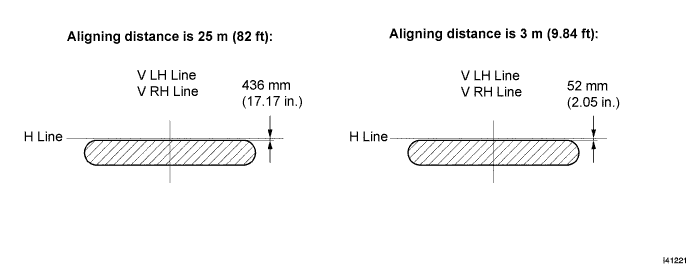
| 12. FOG LIGHT AIMING ADJUSTMENT |
Adjust the fog light aim into the specified range by turning aiming screw with a screwdriver.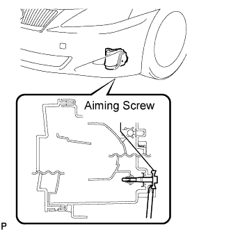
- NOTICE:
- The final turn of the aiming screw should be made in the clockwise direction. If the screw is tightened excessively, loosen it and then retighten it, so that the final turn of the screw is in the clockwise direction.