P1235
Diagnostic trouble codes
DESCRIPTION
The high pressure side fuel pump is attached to the insulator, which is attached to the cylinder head cover. The pump activates according to the position of the cam on the exhaust side camshaft (right bank).The high pressure side fuel pump increase the pressure of the fuel supplied from the fuel pump in the fuel tank to 4 to 13 MPa (40.8 to 132.6 kgf/cm, 580 to 1,885 psi) according to the operating condition, and it feeds the fuel to the fuel delivery pipe.
| DTC No. |
DTC Detection Condition |
Trouble Area |
| P1235 |
Open or short in high pressure side fuel pump circuit for 1 second or more (1 trip detection logic) |
|
WIRING DIAGRAM
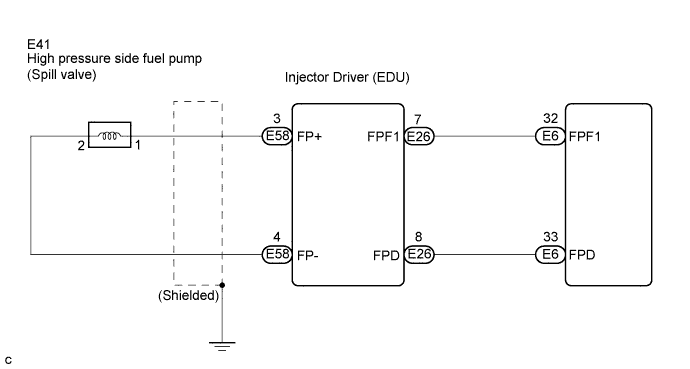

INSPECTION PROCEDURE
- HINT:
- Read freeze frame data using the intelligent tester. Freeze frame data records the engine conditions when malfunctions are detected. When troubleshooting, freeze frame data can help determine if the vehicle was running or stopped, if the engine was warmed up or not, if the air-fuel ratio was lean or rich, and other data from the time the malfunction occurred (Click here).
| 1. INSPECT FUEL PUMP FOR HIGH PRESSURE |

Disconnect the E41 fuel pump for high pressure connector.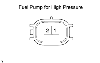
Measure the resistance of the fuel pump for high pressure.
- Standard resistance:
Tester Connection
Condition
Specified Condition
1 - 2
20°C (68°F)
1.19 to 1.39 Ω
Reconnect the fuel pump for high pressure connector.
|
|
||||

| OK | |
 |
| 2. CHECK HARNESS AND CONNECTOR (INJECTOR DRIVER - HIGH PRESSURE SIDE FUEL PUMP) |
Disconnect the E58 injector driver (EDU) connector.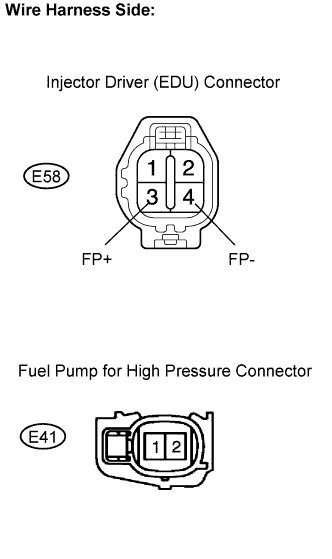
Disconnect the E41 high pressure side fuel pump connector.
Measure the resistance of the wire harness side connectors.
- Standard resistance (Check for open):
Tester Connection
Specified Condition
FP+ (E58-3) - E41-1
Below 1 Ω
FP- (E58-4) - E41-2
Below 1 Ω
- Standard resistance (Check for short):
Tester Connection
Specified Condition
FP+ (E58-3) or E41-1 - Body ground
10 kΩ or higher
FP- (E58-4) or E41-2 - Body ground
10 kΩ or higher
Reconnect the injector driver (EDU) connector.
Reconnect the high pressure side fuel pump connector.
|
|
||||
| OK | |
|
| 3. INSPECT ECM (FPD AND FPF1 VOLTAGE) |
Start the engine, and check the waveforms between terminals FPF1 and E1, and FPD and E1 of the E6 and E4 ECM connectors.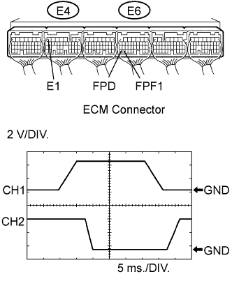
- HINT:
- The correct waveform is as shown in the illustration.
| ECM Terminal Name |
CH1: FPD (E6-33) - E1 (E4-7) CH2: FPF1 (E6-32) - E1 (E4-7) |
| Tester Range |
2 V/DIV. 5 ms./DIV. |
| Conditions |
Idling with warm engine |
|
|
||||
| NG | |
|
| 4. CHECK HARNESS AND CONNECTOR (INJECTOR DRIVER - ECM) |
Disconnect the E6 ECM connector.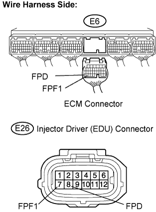
Disconnect the E26 injector driver (EDU) connector.
Measure the resistance of the wire harness side connectors.
- Standard resistance (Check for open):
Tester Connection
Specified Condition
FPF1 (E6-32) - FPF1 (E26-7)
Below 1 Ω
FPD (E6-33) - FPD (E26-8)
Below 1 Ω
- Standard resistance (Check for short):
Tester Connection
Specified Condition
FPF1 (E6-32) or FPF1 (E26-7) - Body ground
10 kΩ or higher
FPD (E6-33) or FPD (E26-8) - Body ground
10 kΩ or higher
Reconnect the ECM connector.
Reconnect the injector driver (EDU) connector.
|
|
||||
| OK | ||
 |
||
| ||