P1550
Diagnostic trouble codes
DESCRIPTION
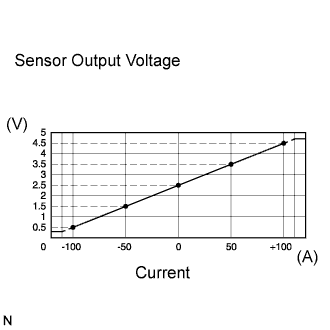

The battery current sensor installed on the positive (+) battery terminal detects the amount of current supplied from the generator.
The battery current sensor changes current to voltage (at the positive (+) battery terminal) and sends it to the ECM. The ECM controls the voltage of the generator based on the signals from the battery current sensor.
| DTC No. |
DTC Detection Condition |
Trouble Area |
| P1550 |
The following condition continues for 10 seconds or more with the engine switch on (IG) (1 trip detection logic):
|
|
| P1551 |
Battery current sensor output value is 0.2 V or less for 0.5 seconds or more with the engine switch on (IG) (1 trip detection logic): |
|
| P1552 |
Battery current sensor output value is 4.8 V or more for 0.5 seconds or more with the engine switch on (IG) (1 trip detection logic): |
|
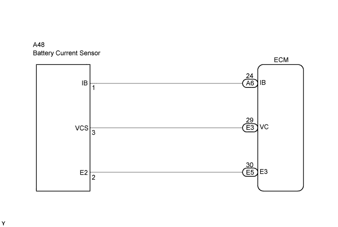
WIRING DIAGRAM
INSPECTION PROCEDURE
- HINT:
- If different DTCs that are related to a different system are output simultaneously while terminal E3 is used as a ground terminal, terminal E3 may be open.
- Read freeze frame data using the intelligent tester. Freeze frame data records the engine conditions when malfunctions are detected. When troubleshooting, freeze frame data can help determine if the vehicle was running or stopped, if the engine was warmed up or not, if the air-fuel ratio was lean or rich, and other data from the time the malfunction occurred (Click here).
- If different DTCs that are related to a different system are output simultaneously while terminal E3 is used as a ground terminal, terminal E3 may be open.
| 1. INSPECT BATTERY CURRENT SENSOR ASSEMBLY |

Disconnect the A48 battery thermometer sensor connector.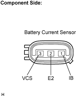
Measure the resistance of the battery current sensor.
- Standard resistance:
Tester Connection
Specified Condition
VC5 (3) - E2 (2)
3 to 6 or 0.7 to 8 kΩ
VC5 (3) - IB (1)
0.2 to 0.3 or 0.2 to 3 kΩ
IB (1) - E2 (2)
1.5 to 8 or 3 to 6 kΩ
- HINT:
- The resistance differs according to the tester type.
|
|
||||

| OK | |
 |
| 2. CHECK HARNESS AND CONNECTOR (BATTERY CURRENT SENSOR - ECM) |
Check the harness and the connectors between the ECM and the battery current sensor.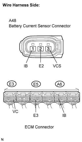
Disconnect the battery current sensor connector.
Disconnect the A6, E3 and E5 ECM connectors.
Measure the resistance of the wire harness side connectors.
- Standard resistance (Check for open):
Tester Connection
Specified Condition
IB (A48-1) - IB (A6-24)
Below 1 Ω
VC5 (A48-3) - VC (E3-29)
Below 1 Ω
E2 (A48-2) - E3 (E5-30)
Below 1 Ω
- Standard resistance (Check for short):
Tester Connection
Specified Condition
IB (A48-1) or IB (A6-24) - Body ground
10 kΩ or higher
VC5 (A48-3) or VC (E3-29) - Body ground
10 kΩ or higher
|
|
||||
| OK | ||
 |
||
| ||