B2274
Diagnostic trouble codes
DESCRIPTION
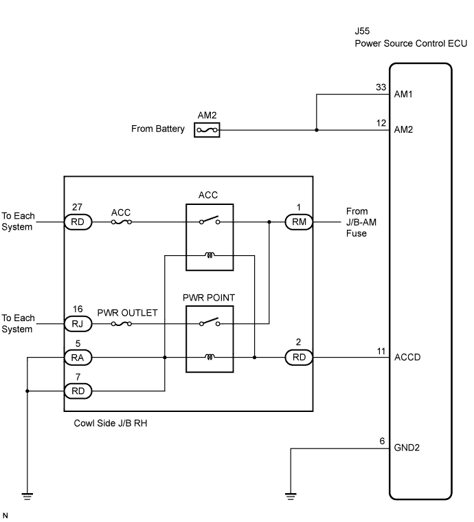
This DTC is output when there is a problem in the ACC output circuit, which is from the inside of the power source control ECU to the ACC or PWR POINT relay.- HINT:
- When the power source control ECU is replaced with a new one and the negative (-) battery terminal is connected, the power source mode becomes the IG-ON mode. When the battery is removed and reinstalled, the power source mode that was selected when the battery was removed is restored.
| DTC No. |
DTC Detection Condition |
Trouble Area |
| B2274 |
ACC relay actuation circuit inside power source control ECU or other related circuit is malfunctioning |
|
WIRING DIAGRAM

INSPECTION PROCEDURE
| 1. INSPECT FUSE (AM2) |

Remove the AM2 fuse from the cowl side J/B RH.
Measure the resistance of the fuse.
- Standard resistance:
- Below 1 Ω
|
|
||||

| OK | |
 |
| 2. CHECK CONNECTORS |
Check that the connectors are securely connected and the terminals are not deformed or loose.
- OK:
- The connectors are securely connected and the terminals are not deformed or loose.
|
|
||||
| OK | |
|
| 3. CHECK WIRE HARNESS (POWER SOURCE CONTROL ECU - BATTERY AND BODY GROUND) |
Disconnect the J55 ECU connector.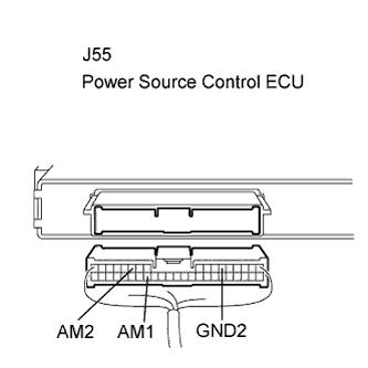
Measure the voltage according to the value(s) in the table below.
- Standard voltage:
Tester Connection (Symbols)
Condition
Specified Condition
J55-33 (AM1) - Body ground
Always
10 to 14 V
J55-12 (AM2) - Body ground
Always
10 to 14 V
Measure the resistance according to the value(s) in the table below.
- Standard resistance:
Tester Connection (Symbols)
Condition
Specified Condition
J55-6 (GND2) - Body ground
Always
Below 1 Ω
|
|
||||
| OK | |
|
| 4. CHECK COWL SIDE JUNCTION BLOCK RH (ACC RELAY, PWR OUTLET RELAY) |
Disconnect the RD and RA J/B connectors.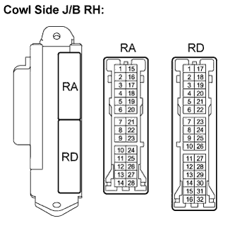
Measure the resistance according to the value(s) in the table below.
- Standard resistance:
Tester Connection (Symbols)
Condition
Specified Condition
RD-2 - RA-5 or RD-7
Always
68 to 250 Ω at 20°C (68°F)
|
|
||||

| OK | |
|
| 5. CHECK WIRE HARNESS (POWER SOURCE CONTROL ECU - BATTERY AND BODY GROUND) |
Measure the resistance according to the value(s) in the table below.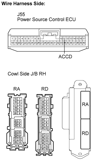
- Standard resistance:
Tester Connection (Symbols)
Condition
Specified Condition
J55-11 (ACCD) - RD-2
Always
Below 1 Ω
J55-11 (ACCD) - Body ground
Always
10 kΩ or higher
RA-5 - Body ground
Always
Below 1 Ω
RD-7 - Body ground
Always
Below 1 Ω
Connect each J/B connector with the power source control ECU connector disconnected.
Measure the voltage according to the value(s) in the table below.
- Standard voltage:
Tester Connection (Symbols)
Condition
Specified Condition
J55-11 (ACCD) - Body ground
Engine switch on (IG)
Below 1 V
|
|
||||
| OK | |
|
| 6. INSPECT POWER SOURCE CONTROL ECU |
Reconnect the J55 ECU connector.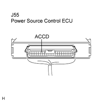
Measure the voltage according to the value(s) in the table below.
- Standard voltage:
Tester Connection (Symbols)
Condition
Specified Condition
J55-11 (ACCD) - Body ground
Engine switch off
Below 1 V
Engine switch on (IG)
8 to 14 V
|
|
||||
| OK | |
|
| 7. RECHECK FOR DTC |
Delete the DTCs (Click here).
Check for DTCs again.
- OK:
- DTC B2274 is not output.
|
|
||||
| OK | ||
 |
||
| ||
| 8. REPLACE FAULTY J/B AND CHECK POWER SOURCE CONTROL ECU |
Replace a faulty J/B and then connector the power source control ECU connector.
Measure the voltage according to the value(s) in the table below.
- Standard voltage:
Tester Connection (Symbols)
Condition
Specified Condition
J55-11 (ACCD) - Body ground
Engine switch off
Below 1 V
Engine switch on (IG)
8 to 14 V
|
|
||||
| OK | ||
|
||
| ||
| 9. REPAIR OR REPLACE WIRE HARNESS OR CONNECTOR AND CHECK POWER SOURCE CONTROL ECU |
Repair or replace a faulty wire harness or connector and then connect the power source control ECU connector.
Measure the voltage according to the value(s) in the table below.
- Standard voltage:
Tester Connection (Symbols)
Condition
Specified Condition
J55-11 (ACCD) - Body ground
Engine switch off
Below 1 V
Engine switch on (IG)
8 to 14 V
|
|
||||
| OK | ||
|
||
| ||