TERMINALS OF ECU
System information
| Terminal of ECU |
(*2): A/T
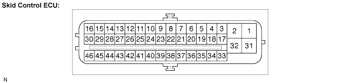

| Symbols (Terminal No.) |
Terminal Description |
| GND2 (1) |
Pump motor ground |
| BM (2) |
Motor relay input |
| FR+ (3) |
Front wheel speed RH signal power supply output |
| FL- (4) |
Front wheel speed LH signal input |
| RR+ (5) |
Rear wheel speed RH signal power supply output |
| RL- (6) |
Rear wheel speed LH signal input |
| FSW+ (7) |
Brake pedal load sensing switch input |
| CANH (11) |
CAN communication line H |
| SP1 (12) |
Speed signal output for combination meter |
| D/G (13) |
Diagnosis tester communication line |
| MRF (14) |
Fail safe motor relay output |
| MR (15) |
Motor relay output |
| STPO (16) (*2) |
Stop light control relay output |
| FR- (17) |
Front wheel speed RH signal input |
| FL+ (18) |
Front wheel speed LH signal power supply output |
| RR- (19) |
Rear wheel speed RH signal input |
| RL+ (20) |
Rear wheel speed LH signal power supply output |
| STP2 (21) (*2) |
Stop light control relay input |
| TS (24) |
Test mode (sensor signal check) input |
| CANL (25) |
CAN communication line L |
| STP1 (27) |
Stop light switch input |
| PKB (28) |
Parking brake switch input |
| BZ (30) |
Skid control buzzer output |
| +BS (31) |
Solenoid relay power supply |
| GND1 (32) |
Skid control ECU ground |
| FRO (37) (*1) |
Front wheel speed RH signal output |
| FLO (38) (*1) |
Front wheel speed LH signal output |
| WFSE (42) |
WFSE input |
| CSW (43) |
Traction OFF switch input |
| R+ (45) |
Power supply for motor relay |
| IG1 (46) |
IG1 power supply |
| Terminal Inspection |
Disconnect the connector and measure the voltage or resistance on the wire harness side.
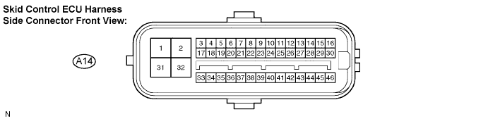
- HINT:
- Voltage cannot be measured with the connector connected to the skid control ECU because the connector is watertight.
- Standard:
Symbols (Terminal No.)
Wiring Color
Terminal Description
Condition
Specified Condition
GND2 (A14-1) - Body ground
W-B - Body ground
Pump motor ground
Engine switch off
Below 1 Ω
FSW+ (A14-7) - Body ground
G-O - Body ground
Brake pedal load sensing switch input
Stop light switch ON → OFF (Brake pedal depressed → released)
0.9 to 1.1 kΩ→ 192 to 234 Ω
STP2 (A14-21) (*1) - Body ground
R-B - Body ground
Stop light control relay output
Stop light switch ON → OFF (Brake pedal depressed → released)
8 to 16 V → Below 1.5 V
PKB (A14-28) - Body ground
Y - Body ground
Parking brake switch input
Engine switch on (IG), parking brake switch ON → OFF
Below 1 Ω → 10 kΩ or higher
BZ (A14-30) - Body ground
Y-B - Body ground
Buzzer output
Engine switch on (IG), when buzzer not sounding
6 to 10 V
+BS (A14-31) - Body ground
BR - Body ground
Solenoid relay power supply
Always
10 to 14 V
GND1 (A14-32) - Body ground
W-B - Body ground
Skid control ECU ground
Always
Below 1 Ω
CSW (A14-43) - Body ground
L-Y - Body ground
Traction OFF switch input
Traction OFF switch held ON → OFF (Not pressed)
Below 1 Ω → 10 kΩ or higher
IG1 (A14-46) - Body ground
B-W - Body ground
IG1 power supply
Engine switch on (IG)
10 to 14 V