TERMINALS OF ECU
System information
| CHECK POWER SOURCE CONTROL ECU |


Disconnect the J55 ECU connector.
Measure the voltage and resistance of the wire harness side connector.
If the result is not as specified, there may be a malfunction on the wire harness side.Symbols (Terminal No.)
Wiring Color
Terminal Description
Condition
Specified Condition
AM1 (J55-33) - Body ground
O - Body ground
+B power supply
Always
10 to 14 V
AM2 (J55-12) - Body ground
O - Body ground
+B power supply
Always
10 to 14 V
SSW1 (J55-14) - Body ground
B - Body ground
Engine switch signal
Engine switch pushed
Below 1 Ω
SSW1 (J55-14) - Body ground
B - Body ground
Engine switch signal
Engine switch not pushed
10 kΩ or higher
SSW2 (J55-37) - Body ground
SB - Body ground
Engine switch signal
Engine switch pushed
Below 1 Ω
SSW2 (J55-37) - Body ground
SB - Body ground
Engine switch signal
Engine switch not pushed
10 kΩ or higher
GND2 (J55-6) - Body ground
W-B - Body ground
Ground
Always
Below 1 Ω
LIN1 (J55-30) - Body ground
V - Body ground
LIN line
Always
10 kΩ or higher
MPX1 (J55-7) - Body ground
GR - Body ground
MPX line
Always
10 kΩ or higher
MPX2 (J55-24) - Body ground
GR - Body ground
MPX line
Always
10 kΩ or higher
Reconnect the J55 ECU connector.
Measure the voltage of the connector.
Symbols (Terminal No.)
Wiring Color
Terminal Description
Condition
Specified Condition
ACCD (J55-11) - GND2 (J55-6)
LG - W-B
ACC signal
Engine switch on (ACC)
8 to 14 V
ACCD (J55-11) - GND2 (J55-6)
LG - W-B
ACC signal
Engine switch off
Below 1 V
IG1D (J55-34) - GND2 (J55-6)
P - W-B
IG1 signal
Engine switch on (IG)
8 to 14 V
IG1D (J55-34) - GND2 (J55-6)
P - W-B
IG1 signal
Engine switch on (ACC)
Below 1 V
IG2D (J55-35) - GND2 (J55-6)
LG - W-B
IG2 signal
Engine switch on (IG)
8 to 14 V
IG2D (J55-35) - GND2 (J55-6)
LG - W-B
IG2 signal
Engine switch on (ACC)
Below 1 V
STP (J55-1) - GND2 (J55-6)
R - W-B
Stop light signal
Brake pedal depressed
8 to 14 V
STP (J55-1) - GND2 (J55-6)
R - W-B
Stop light signal
Brake pedal released
Below 1 V
SLR+ (J55-32) - GND2 (J55-6)
W - W-B
Steering lock motor signal
Steering lock motor operating
Below 1 V
SLR+ (J55-32) - GND2 (J55-6)
W - W-B
Steering lock motor signal
Steering lock motor does not operate
10 to 14 V
SLP (J55-26) - GND2 (J55-6)
R - W-B
Steering lock actuator position signal
Steering lock is locked
Pulse generation
(See waveform 3)
SLP (J55-26) - GND2 (J55-6)
R - W-B
Steering lock actuator position signal
Steering lock is released
Pulse generation
(See waveform 3)
SPD (J55-19) - GND2 (J55-6)
P - W-B
Vehicle speed signal
Engine switch on (IG), rotate rear wheel slowly
Pulse generation
(See waveform 1)
TACH (J55-2) - GND2 (J55-6)
W - W-B
Tachometer signal
Engine running
Pulse generation
(See waveform 2)
P (J55-5) - GND2 (J55-6) *3
BR - W-B
Shift lock signal
Shift lever P position
8 to 14 V
P (J55-5) - GND2 (J55-6) *3
BR - W-B
Shift lock signal
Shift lever not P position
Below 1 V
CTSW (J55-31) - GND2 (J55-6)
LG - W-B
Starter assist signal
Brake pedal depressed, shift lever P position, engine switch is pushed once → on (IG)
0.1 to 0.8 V *1
→ 8 to 14 V
STSW (J55-39) - GND2 (J55-6)
L - W-B
Starter activation request signal
Brake pedal (A/T) or clutch pedal (M/T) depressed, engine switch hold on (ST)
8 to 14 V *2
STR1 (J55-17) - GND2 (J55-6)
SB - W-B
Park/neutral position switch
Shift lever P or N (A/T) position
Clutch pedal depressed (M/T)
Below 1 V
STR2 (J55-15) - GND2 (J55-6)
V - W-B
Starter signal
Brake pedal (A/T) or clutch pedal (M/T) depressed, shift lever P or N position (A/T), engine switch on (ST)
8 to 14 V *2
INDS (J55-4) - GND2 (J55-6)
L - W-B
Vehicle condition signal
Brake pedal (A/T) or clutch pedal (M/T) depressed, shift lever P position (A/T).
8 to 14 V
INDW (J55-13) - GND2 (J55-6)
BR - W-B
Warning signal
Brake pedal (A/T) or clutch pedal (M/T) depressed, shift lever P position (A/T), engine switch on (ACC, IG)
8 to 14 V
SWIL (J55-36) - GND2 (J55-6)
Y - W-B
Illumination signal
Light control switch TAIL or HEAD
8 to 14 V
SKSW (J55-28) - GND2 (J55-6)
B - W-B
Key in vehicle signal
Engine switch on (ACC, IG)
Below 1 V
- HINT:
- *1: Voltage is output only when the engine is cranking.
- *2: Voltage is output for 0.3 seconds when engine is cranking start. Disconnect the E4 connector from the ECM before measuring the voltage.
- *3: A/T
Using an oscilloscope, check the signal waveform of the ECU.
Waveform 1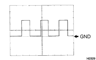
Waveform 1 (Reference): Terminal No.
J55-19 - Body ground
Tool Setting
5 V/DIV., 10 ms./DIV.
Vehicle Condition
Driving at approx. 20 km/h (12 mph)
- HINT:
- As the engine revolution speed increases, the wavelength shortens.
Waveform 2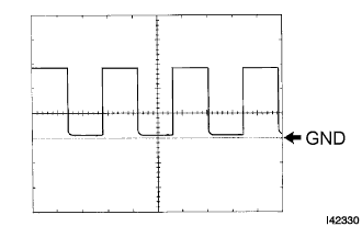
Waveform 2 (Reference): Terminal No.
J55-2 - Body ground
Tool Setting
5 V/DIV., 10 ms./DIV.
Vehicle Condition
Engine idling
- HINT:
- As the vehicle speed increases, the wavelength shortens.
Waveform 3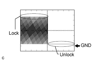
Waveform 3 (Reference): Terminal No.
J55-26 - Body ground
Tool Setting
2 V/DIV., 100 ms./DIV.
Vehicle Condition
Steering lock / unlock
- HINT:
- As the steering lock increases, the wavelength shortens.
| CHECK CERTIFICATION ECU |

Disconnect the P33 ECU connector.
Measure the voltage and resistance of the wire harness side connector.
If the result is not as specified, there may be a malfunction on the wire harness side.Symbols (Terminal No.)
Wiring Color
Terminal Description
Condition
Specified Condition
+B1 (P33-1) - Body ground
L - Body ground
+B power supply
Always
10 to 14 V
IG (P33-18) - Body ground
B - Body ground
Ignition power supply
Engine switch on (IG)
10 to 14 V
IG (P33-18) - Body ground
B - Body ground
Ignition power supply
Engine switch off
Below 1 V
LIN (P33-10) - Body ground
V - Body ground
LIN line
Always
10 kΩ or higher
E (P33-17) - Body ground
W-B - Body ground
Ground
Always
Below 1 Ω
| CHECK ECM |
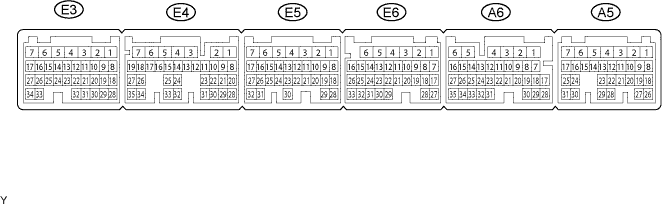
Disconnect the A5, E5, E4, E3 and E6 ECM connectors.
Measure the voltage and resistance of the wire harness side connectors.
If the result is not as specified, there may be a malfunction on the wire harness side.Symbols (Terminal No.)
Wiring Color
Terminal Description
Condition
Specified Condition
+B (A5-6) - Body ground
B-R - Body ground
Power source of ECM
Engine switch on (IG)
10 to 14 V
+B1 (A5-5) - Body ground
B-R - Body ground
Power source of ECM
Engine switch on (IG)
10 to 14 V
IGSW (A5-17) - Body ground
B-W - Body ground
Ignition switch signal
Engine switch on (IG)
10 to 14 V
E01 (E5-2) - Body ground
W-B - Body ground
Ground
Always
Below 1 Ω
E02 (E5-1) - Body ground
W-B - Body ground
Ground
Always
Below 1 Ω
E03 (E3-6) - Body ground
W-B - Body ground
Ground
Always
Below 1 Ω
E04 (E6-5) - Body ground
W-B - Body ground
Ground
Always
Below 1 Ω
E05 (E6-3) - Body ground
W-B - Body ground
Ground
Always
Below 1 Ω
E1 (E4-7) - Body ground
BR - Body ground
Ground
Always
Below 1 Ω
EC (A5-2) - Body ground
W-B - Body ground
Ground
Always
Below 1 Ω
ME01 (E3-4) - Body ground
W-B - Body ground
Ground
Always
Below 1 Ω
Reconnect the A5, E5, E4, E3 and E6 ECM connectors.
Measure the voltage of the connectors.
If the result is not as specified, the ECM may have a malfunction.Symbols (Terminal No.)
Wiring Color
Terminal Description
Condition
Specified Condition
STA (A5-12) - E1 (E4-7)
R - BR
Starter relay operation signal
Cranking
10 to 14 V
ACCR (A5-11) - E1 (E4-7)
W-L - BR
ACC relay cut signal (output)
Engine switch on (IG)
10 to 14 V
TACH (A6-16) - E1 (E4-7)
R-W - BR
Engine revolution signal (output)
Idling
Pulse generation (see waveform 1)
STP (A6-4) - E1 (E4-7)
R-B - BR
Stop light switch signal (input)
Brake pedal depressed
7.5 to 14 V
STP (A6-4) - E1 (E4-7)
R-B - BR
Stop light switch signal (input)
Brake pedal released
Below 1.5 V
STAR (E4-4) - E1 (E4-7)
L-Y - BR
PNP switch signal (input)
Engine switch on (IG), shift position P or N
10 to 14 V
KSW (A5-23) - E1 (E4-7)
L-R - BR
Engine switch signal (input)
Engine switch off
4 to 6 V
KSW (A5-23) - E1 (E4-7)
L-R - BR
Engine switch signal (input)
When engine switch is pushed once
10 to 14 V
KSW (A5-23) - E1 (E4-7)
L-R - BR
Engine switch signal (input)
Engine switch on (ACC)
Below 1.5 V
Using an oscilloscope, check the signal waveform of the ECM.
Waveform 1 (Reference): Terminal No.
A6-16 - E7-4
Tool Setting
5 V/DIV., 10 ms./DIV.
Vehicle Condition
Engine idling
- HINT:
- As the vehicle speed increases, the wavelength shortens.
| CHECK STEERING LOCK ECU |
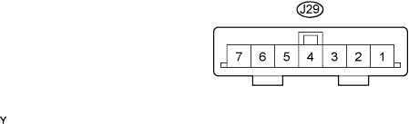
Disconnect the J29 ECU connector.
Measure the voltage and resistance of the wire harness side connector.
Symbols (Terminal No.)
Wiring Color
Terminal Description
Condition
Specified Condition
B (J29-7) - Body ground
O - Body ground
+B power supply
Always
10 to 14 V
IG2 (J29-6) - Body ground
LG - Body ground
Ignition power supply
Engine switch on (IG)
10 to 14 V
IG2 (J29-6) - Body ground
LG - Body ground
Ignition power supply
Engine switch off
Below 1 V
GND (J29-1) - Body ground
W-B - Body ground
Ground
Always
Below 1 Ω
SGND (J29-2) - Body ground
W-B - Body ground
Ground
Always
Below 1 Ω
- If the result is not as specified, there may be a malfunction on the wire harness side.
- If the result is not as specified, there may be a malfunction on the wire harness side.
Reconnect the J29 ECU connector.
Measure the voltage of the connector.
Symbols (Terminal No.)
Wiring Color
Terminal Description
Condition
Specified Condition
SLP1 (J29-4) - GND (J29-1)
R - W-B
Steering lock actuator position signal
Steering is locked
10 to 14 V
SLP1 (J29-4) - GND (J29-1)
R - W-B
Steering lock actuator position signal
Steering is released
Below 1 V
- If the result is not as specified, the ECU may have a malfunction.
- If the result is not as specified, the ECU may have a malfunction.