C0273/13
Diagnostic trouble codes
DESCRIPTION
If a DTC of the motor line is stored, the ABS MOTOR1 (fail safe) relay cuts off the power supply to the ABS MOTOR2 relay and performs fail safe.While any of the ABS, TRC, VSC, or BA is operating, the skid control ECU (housed in the actuator assembly) turns the ABS MOTOR2 relay on and activates the pump motor in the brake actuator.
This code may be stored if the motor relay (+BM) voltage becomes lower than the DTC detecting condition due to insufficient output from the battery or alternator.
| DTC No. |
DTC Detection Condition |
Trouble Area |
| C0273/13 |
When any of the following (1 or 2) is detected:
|
|
| C0274/14 |
When the motor relay is OFF, the ABS MOTOR2 relay remains closed for 4 seconds or more. |
|
| C1361/91 |
Immediately after the engine switch is turned on (IG), the relay contact is closed for 4 seconds when the ABS MOTOR1 (fail safe) relay is OFF. |
|
WIRING DIAGRAM
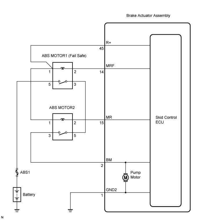

INSPECTION PROCEDURE
- NOTICE:
- When replacing the brake actuator assembly, perform zero point calibration (Click here).
| 1. INSPECT ABS1 FUSE |

Remove the ABS1 fuse from engine room No. 1 R/B.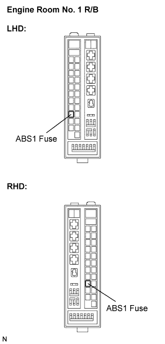
Measure the resistance according to the value(s) in the table below.
- Standard resistance:
Tester Connection
Condition
Specified Condition
ABS1 (50A) fuse
Always
Below 1 Ω
|
|
||||

| OK | |
 |
| 2. INSPECT ABS MOTOR2 RELAY |
Install the ABS1 fuse.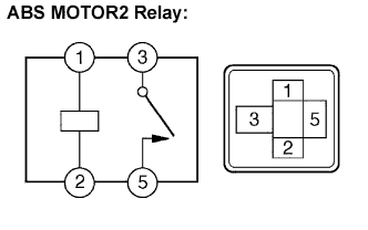
Remove the ABS MOTOR2 relay.
Measure the resistance according to the value(s) in the table below.
- Standard resistance:
Tester Connection
Condition
Specified Condition
3 - 5
Always
10 kΩ or higher
3 - 5
Apply B+ between terminals 1 and 2
Below 1 Ω
|
|
||||
| OK | |
|
| 3. INSPECT ABS MOTOR1 (FAIL SAFE) RELAY |
Remove the ABS MOTOR1 (fail safe) relay.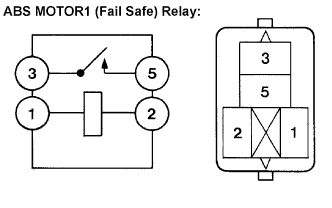
Measure the resistance according to the value(s) in the table below.
- Standard resistance:
Tester Connection
Condition
Specified Condition
3 - 5
Always
10 kΩ or higher
3 - 5
Apply B+ between terminals 1 and 2
Below 1 Ω
|
|
||||
| OK | |
|
| 4. INSPECT ENGINE ROOM NO. 3 RELAY BLOCK (POWER SOURCE TERMINAL) |
Measure the voltage according to the value(s) in the table below.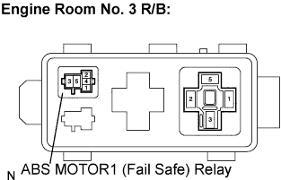
- Standard voltage:
Tester Connection
Condition
Specified Condition
ABS MOTOR1 (fail safe) relay terminal 5 - Body ground
Always
10 to 14 V
|
|
||||
| OK | |
|
| 5. INSPECT ENGINE ROOM NO. 3 RELAY BLOCK |
Measure the resistance according to the value(s) in the table below.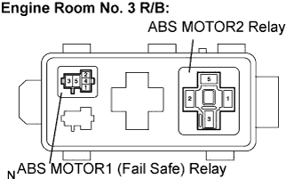
- Standard resistance:
Tester Connection
Condition
Specified Condition
ABS MOTOR1 (fail safe) relay terminal 3 - ABS MOTOR2 relay terminal 5
Always
Below 1 Ω
ABS MOTOR1 (fail safe) relay terminal 3 - Body ground
Always
10 kΩ or higher
|
|
||||
| OK | |
|
| 6. CHECK HARNESS AND CONNECTOR (SKID CONTROL ECU - ENGINE ROOM NO. 3 RELAY BLOCK) |
Disconnect the skid control ECU connector.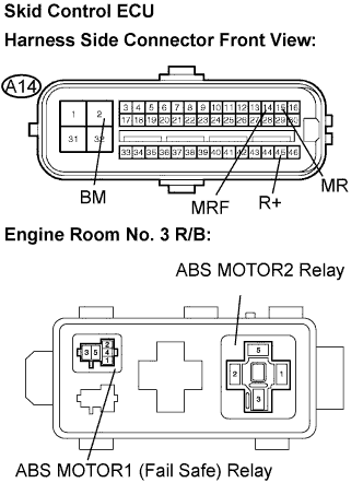
Measure the resistance according to the value(s) in the table below.
- Standard resistance:
Tester Connection
Condition
Specified Condition
A14-2 (BM) - ABS MOTOR2 relay terminal 3
Always
Below 1 Ω
A14-2 (BM) - Body ground
Always
10 kΩ or higher
A14-14 (MRF) - ABS MOTOR1 (fail safe) relay terminal 2
Always
Below 1 Ω
A14-14 (MRF) - Body ground
Always
10 kΩ or higher
A14-15 (MR) - ABS MOTOR2 relay terminal 2
Always
Below 1 Ω
A14-15 (MR) - Body ground
Always
10 kΩ or higher
A14-45 (R+) - ABS MOTOR1 (fail safe) relay terminal 1
Always
Below 1 Ω
A14-45 (R+) - Body ground
Always
10 kΩ or higher
|
|
||||
| OK | |
|
| 7. RECONFIRM DTC |
Clear the DTC (Click here).
Start the engine.
Drive the vehicle at the speed of 4 mph (6 km/h) or more.
Check if the same DTC is recorded (Click here).
- HINT:
- Reinstall the relays, connectors, etc. and restore the vehicle to its prior condition before rechecking for DTCs.
- Result:
Condition
Proceed to
DTCs (C0273/13, C0274/14 and/or C1361/91) are not output
A
DTCs (C0273/13, C0274/14 and/or C1361/91) are output
B
- HINT:
- If a speed signal of 4 mph (6 km/h) or more is input to the skid control ECU, with the engine switch on (IG) and the stop light switch off, the ECU performs self diagnosis of the motor and solenoid circuits.
- If the normal system code is output (the trouble code is not output), slightly jiggle the connectors, wire harness, and fuses of the brake actuator assembly. Make sure that no DTCs are output.
- If any DTCs are output while jiggling a connector or wire harness of the brake actuator (skid control ECU), inspect and repair the connector or wire harness.
- If a speed signal of 4 mph (6 km/h) or more is input to the skid control ECU, with the engine switch on (IG) and the stop light switch off, the ECU performs self diagnosis of the motor and solenoid circuits.
|
|
||||
| A | ||
 |
||
| ||