Pattern Select Switch Power Mode Circuit
Circuit diagnosis
DESCRIPTION
Cowl side J/B ECU receives pattern select switch information, and sends it through the multiplex communication system and CAN system to the ECM.The ECM memory contains the programs for the NORMAL and POWER shift patterns and lock-up pattern.
By following the programs corresponding to the signals from the pattern select switch, the neutral start and other various sensors, the ECM switches the solenoid valves ON and OFF, and controls the transmission gear change and the lock-up clutch operation.
WIRING DIAGRAM
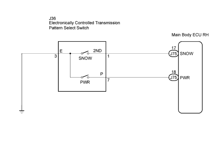

INSPECTION PROCEDURE
| 1. CHECK HARNESS AND CONNECTOR (PATTERN SELECT SWITCH ASSEMBLY - BODY GROUND) |

Disconnect the connector of pattern select switch.
Measure the resistance according to the value(s) in the table below.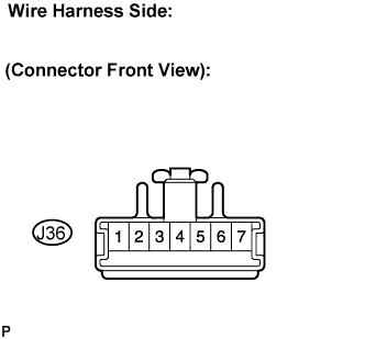
- Standard resistance:
Tester Connection
Specified Condition
3 - Body ground
Below 1 Ω
|
|
||||

| OK | |
 |
| 2. INSPECT PATTERN SELECT SWITCH ASSEMBLY |
Measure the resistance according to the value(s) in the table below.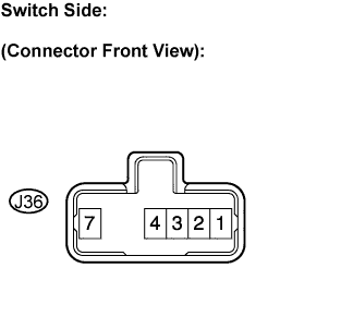
- Standard resistance:
Switch Condition
Tester Connection
Specified Condition
Pattern select switch
(PWR)
3 - 7
Below 1 Ω
Pattern select switch
(NORM)
↑
10 kΩ or higher
|
|
||||
| OK | |
|
| 3. CHECK HARNESS AND CONNECTOR (PATTERN SELECT SWITCH ASSEMBLY - MAIN BODY ECU) |
Connect the connector of pattern select switch.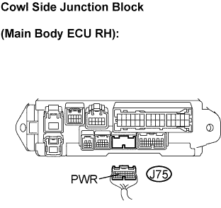
Disconnect the cowl side junction block (main body ECU RH) connector.
Measure the resistance between terminal PWR of the cowl side junction block (main body ECU RH) and body ground.
- Standard resistance:
Switch Condition
Tester Connection
Specified Condition
Pattern select switch
(PWR)
J75 - 18 (PWR) - Body ground
Below 1 Ω
Pattern select switch
(NORM)
↑
10 kΩ or higher
|
|
||||
| OK | ||
 |
||
| ||