Kick Down Switch Circuit
Circuit diagnosis
DESCRIPTION
The kick-down switch is turned ON when the accelerator pedal is fully depressed and a signal is sent to the ECM.When the kick-down switch is turned ON, the ECM controls gear shifting according to the programmed shift diagrams.
If a short circuit develops in the kick-down switch, the ECM disregards the kick-down signals and controls shifting at the normal shift points.
WIRING DIAGRAM
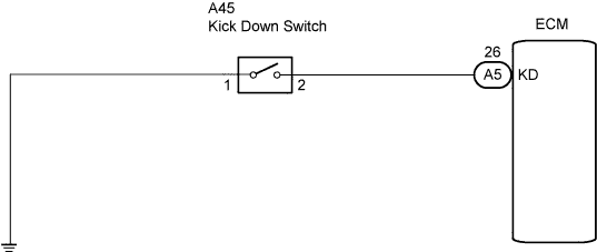

| 1. CHECK HARNESS AND CONNECTOR (KICK DOWN SWITCH - BODY GROUND) |

Disconnect the kick-down switch connector.
Measure the resistance according to the value(s) in the table below.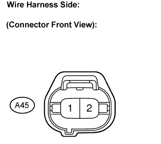
- Resistance:
Tester Connection
Specified Condition
1 - Body ground
Below 1 Ω
|
|
||||

| OK | |
 |
| 2. INSPECT KICK DOWN SWITCH ASSEMBLY |
Measure resistance according to the value(s) in the table below when kick-down switch is ON and OFF.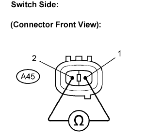
- Resistance:
Switch Condition
Tester Connection
Specified Condition
Press continuously
(Kick-down switch is ON)
1 - 2
Below 1 Ω
Release
(Kick-down switch is OFF)
↑
10 kΩ or higher
|
|
||||
| OK | |
|
| 3. CHECK HARNESS AND CONNECTOR (KICK DOWN SWITCH - ECM) |
Connect the kick-down switch connector.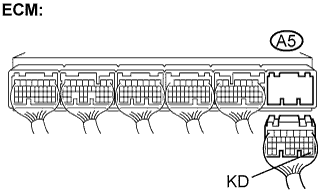
Disconnect the ECM connector.
Measure resistance according to the value(s) in the table below when accelerator pedal is fully depressed or not.
- Resistance:
Switch Condition
Tester Connection
Specified Condition
Fully depressed
(Kick-down switch is ON)
A5 - 26 (KD) - Body ground
Below 1 Ω
Release
(Kick-down switch is OFF)
↑
10 kΩ or higher
|
|
||||
| OK | ||
 |
||
| ||