Engine Switch Indicator Circuit
Circuit diagnosis
DESCRIPTION
Engine start conditions or system malfunctions can be checked by the status of the engine switch indicator light.| Power Source Mode/Condition |
Indicator Light Condition |
||
| Brake pedal released (A/T) Clutch pedal released (M/T) |
Brake pedal depressed, shift lever in P or N (A/T) |
Brake pedal depressed (M/T) |
|
| off |
OFF |
Illuminates ON (Green) |
Illuminates ON (Green) |
| on (ACC, IG) |
Illuminates ON (Amber) |
Illuminates ON (Green) |
Illuminates ON (Green) |
| Engine running |
OFF |
OFF |
OFF |
| Steering lock not unlocked |
Flashes (Green) for 30 sec. |
Flashes (Green) for 30 sec. |
Flashes (Green) for 30 sec. |
| System malfunction |
Flashes (Amber) for 15 sec. |
Flashes (Amber) for 15 sec. |
Flashes (Amber) for 15 sec. |
| Clutch start switch malfunction (M/T) |
Flashes (Green) for 15 sec. |
Flashes (Green) for 15 sec. |
Flashes (Green) for 15 sec. |
WIRING DIAGRAM
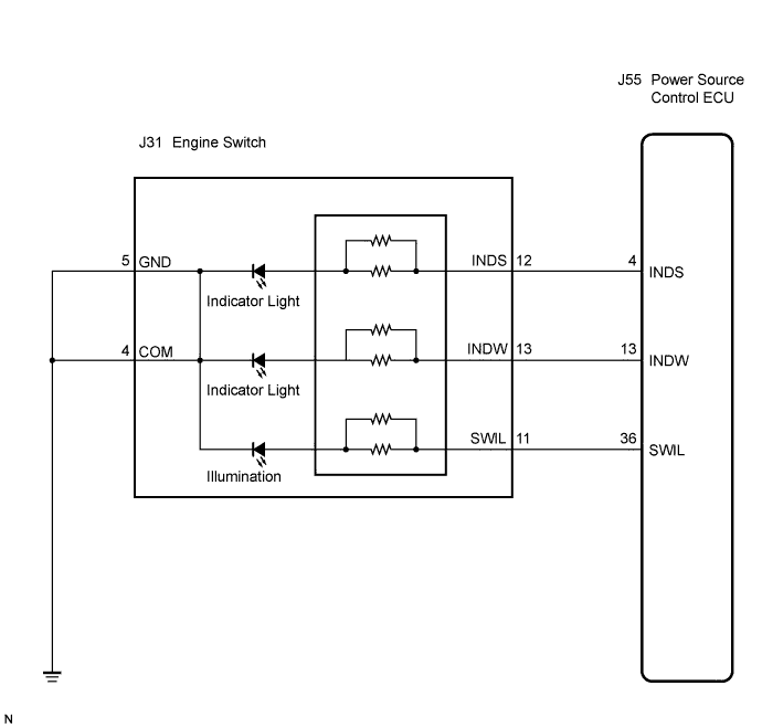

INSPECTION PROCEDURE
| 1. INSPECT ENGINE SWITCH |

Remove the engine switch.
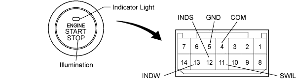
Apply battery voltage between the terminals of the switch, and check the illumination condition of the switch.
- NOTICE:
- If the positive (+) lead and the negative (-) lead are incorrectly connected, the engine switch indicator does not illuminate.
- If the voltage is too low, the indicator will not illuminate.
- If the positive (+) lead and the negative (-) lead are incorrectly connected, the engine switch indicator does not illuminate.
- OK:
Measurement Condition
Specified Condition
Battery positive (+) → Terminal 11 (SWIL)
Battery negative (-) → Terminal 4 (COM) or 5 (GND)
Illuminates
Battery positive (+) → Terminal 12 (INDS)
Battery negative (-) → Terminal 4 (COM) or 5 (GND)
Illuminates
Battery positive (+) → Terminal 13 (INDW)
Battery negative (-) → Terminal 4 (COM) or 5 (GND)
Illuminates
|
|
||||

| OK | |
 |
| 2. CHECK WIRE HARNESS (ENGINE SWITCH - POWER SOURCE CONTROL ECU AND BODY GROUND) |
Disconnect the J31 switch connector.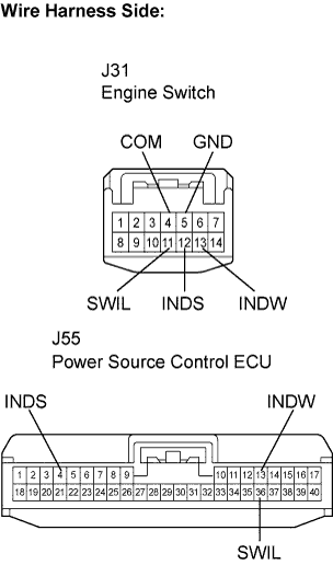
Disconnect the J55 ECU connector.
Measure the resistance according to the value(s) in the table below.
- Standard resistance:
Tester Connection
Condition
Specified Condition
J31-11 (SWIL) - J55-36 (SWIL)
Always
Below 1 Ω
J31-12 (INDS) - J55-4 (INDS)
Always
Below 1 Ω
J31-13 (INDW) - J55-13 (INDW)
Always
Below 1 Ω
J31-5 (GND) - Body ground
Always
Below 1 Ω
J31-4 (COM) - Body ground
Always
Below 1 Ω
J31-11 (SWIL) or J55-36 (SWIL) - Body ground
Always
10 kΩ or higher
J31-12 (INDS) or J55-4 (INDS) - Body ground
Always
10 kΩ or higher
J31-13 (INDW) or J55-13 (INDW) - Body ground
Always
10 kΩ or higher
|
|
||||
| OK | ||
 |
||
| ||