Power Mode does not Change to ON (IG and ACC)
Circuit diagnosis
DESCRIPTION
When the engine switch is pushed with the electrical key in the cabin, the power source control ECU receives signals to switch the power source mode.- HINT:
- To allow use of the intelligent tester to inspect the entry and start system when the engine switch is off, repeat opening and closing any of the doors. Opening and closing a door establishes communication between the intelligent tester and the power source control ECU. (Opening and closing a door can also be simulated by operating a door courtesy light switch.)
WIRING DIAGRAM
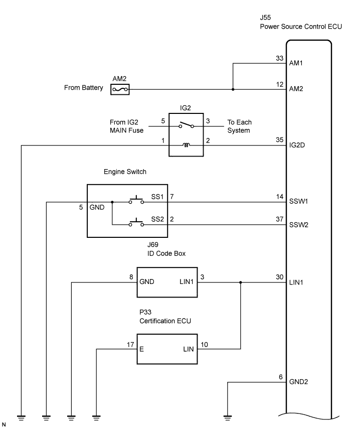

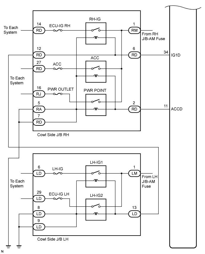
INSPECTION PROCEDURE
| 1. INSPECT FUSE (AM2) |

Remove the AM2 fuse from the cowl side J/B RH.
Measure the resistance of the fuse.
- Standard resistance:
- Below 1 Ω
|
|
||||

| OK | |
 |
| 2. CHECK CONNECTORS |
Check that the connectors are securely connected and the terminals are not deformed or loose.
- OK:
- The connectors are securely connected and the terminals are not deformed or loose.
|
|
||||
| OK | |
|
| 3. CHECK WIRE HARNESS (POWER SOURCE CONTROL ECU - BATTERY AND BODY GROUND) |
Disconnect the J55 ECU connector.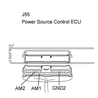
Measure the voltage according to the value(s) in the table below.
- Standard voltage:
Tester Connection (Symbols)
Condition
Specified Condition
J55-33 (AM1) - Body ground
Always
10 to 14 V
J55-12 (AM2) - Body ground
Always
10 to 14 V
Measure the resistance according to the value(s) in the table below.
- Standard resistance:
Tester Connection (Symbols)
Condition
Specified Condition
J55-6 (GND) - Body ground
Always
Below 1 Ω
|
|
||||
| OK | |
|
| 4. CHECK FOR DTCS |
Delete the DTCs (Click here).
- HINT:
- After all the DTCs are cleared, check if the trouble occurs again 5 seconds after the engine switch is turned on (IG).
Check for DTCs again.
- OK:
- No DTC is output.
|
|
||||
| OK | |
|
| 5. READ VALUE OF INTELLIGENT TESTER |
Connect the intelligent tester to the DLC3.
Turn the engine switch on (IG).
Check the DATA LIST for proper functioning of the start switches 1 and 2.
Power source control ECU: Item
Measurement Item/Display (Range)
Normal Condition
Diagnostic Note
St Sw 1
Start Switch 1/ ON or OFF
ON: Engine switch on (IG)
OFF: Engine switch OFF
-
St Sw 2
Start Switch 2/ ON or OFF
ON: Engine switch on (IG)
OFF: Engine switch OFF
-
- OK:
- ON (engine switch on (IG)) and OFF (engine switch off) appear on the screen.
|
|
||||

| OK | |
|
| 6. INSPECT RELAY (IG2) |
Remove the IG2 relay from the engine room R/B No.2.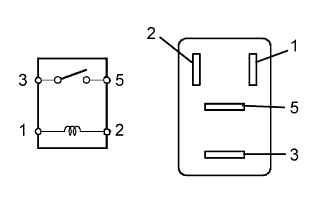
Measure the resistance according to the value(s) in the table below.
- Standard resistance:
Tester Connection
Specified Condition
3 - 5
10 kΩ or higher
3 - 5
Below 1 Ω
(When battery voltage is applied to terminals 1 and 2)
|
|
||||
| OK | |
|
| 7. INSPECT JUNCTION BLOCK (RH-IG RELAY, LH-IG RELAY, ACC RELAY, PWR POINT RELAY) |
RH-IG relay:
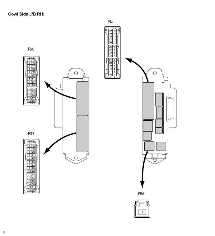
Disconnect the cowl side J/B RH connectors.
Measure the resistance according to the value(s) in the table below.
- Standard resistance:
Tester Connection
Condition
Specified Condition
RD-6 - RA-5 or RD-7
Always
136 to 250 Ω at 20°C (68°F)
RD-6 - Body ground
Always
10 kΩ or higher
RD-2 - RA-5 or RD-7
Always
68 to 250 Ω at 20°C (68°F)
RD-2 - Body ground
Always
10 kΩ or higher
RD-6 - RD-12
Always
Below 1 Ω
RM-1 - RD-14
When battery voltage is applied to terminals RD-6 and RA-5 or RD-7
Below 1 Ω
RM-1 - RD-27
When battery voltage is applied to terminals RD-2 and RA-5 or RD-7
Below 1 Ω
RM-1 - RJ-16
When battery voltage is applied to terminals RD-2 and RA-5 or RD-7
Below 1 Ω
LH-IG relay:
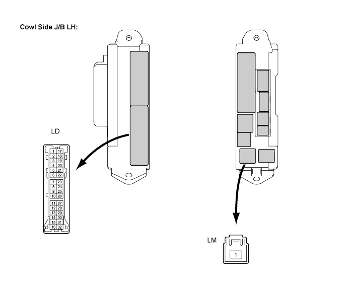
Disconnect the cowl side J/B LH connectors.
Measure the resistance according to the value(s) in the table below.
- Standard resistance:
Tester Connection
Condition
Specified Condition
LD-13 - LD-8 or LD-9
Always
68 to 250 Ω at 20°C (68°F)
LD-13 - Body ground
Always
10 kΩ or higher
LM-1 - LD-6
When battery voltage is applied to terminals LD-13 and LD-8 or LD-9
Below 1 Ω
LM-1 - LD-29
When battery voltage is applied to terminals LD-13 and LD-8 or LD-9
Below 1 Ω
|
|
||||
| OK | |
|
| 8. CHECK WIRE HARNESS |
Inspect the resistance and voltage (Power source control ECU or battery - IG2 relay).
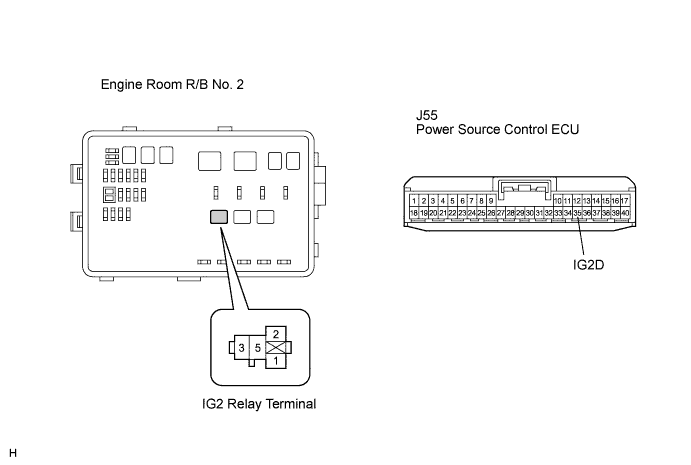
Measure the resistance according to the value(s) in the table below.
- Standard resistance:
Tester Connection (Symbols)
Condition
Specified Condition
J55-35 (IG2D) - IG2 relay terminal 2
Always
Below 1 Ω
IG2 relay terminal 1 - Body ground
Always
Below 1 Ω
J55-35 (IG2D) or IG2 relay terminal 2 - Body ground
Always
10 kΩ or higher
Measure the voltage according to the value(s) in the table below.
- Standard voltage:
Tester Connection
Condition
Specified Condition
IG2 relay terminal 5 - Body ground
Always
10 to 14 V
Inspect the resistance and voltage (Power source control ECU or battery - Cowl side J/B RH).
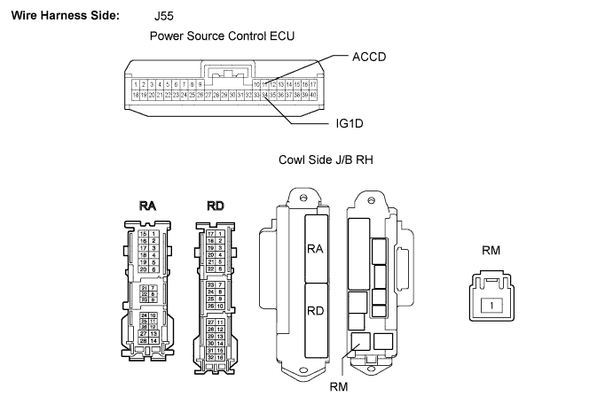
Measure the resistance according to the value(s) in the table below.
- Standard resistance:
Tester Connection (Symbols)
Condition
Specified Condition
J55-34 (IG1D) - RD-6
Always
Below 1 Ω
J55-11 (ACCD) - RD-2
Always
Below 1 Ω
RD-7 - Body ground
Always
Below 1 Ω
RA-5 - Body ground
Always
Below 1 Ω
J55-34 (IG1D) or RD-6 - Body ground
Always
10 kΩ or higher
J55-11 (ACCD) or RD-2 - Body ground
Always
10 kΩ or higher
Measure the voltage according to the value(s) in the table below.
- Standard voltage:
Tester Connection
Condition
Specified Condition
RM-1 - Body ground
Always
10 to 14 V
Inspect the resistance (Cowl side J/B RH - Cowl side J/B LH).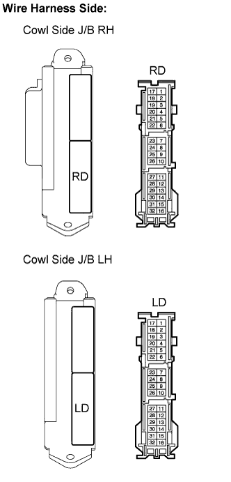
Measure the resistance according to the value(s) in the table below.
- Standard resistance:
Tester Connection (Symbols)
Condition
Specified Condition
RD-12 - LD-13
Always
Below 1 Ω
LD-8 - Body ground
Always
Below 1 Ω
LD-9 - Body ground
Always
Below 1 Ω
Inspect the voltage (Battery - Cowl side J/B LH).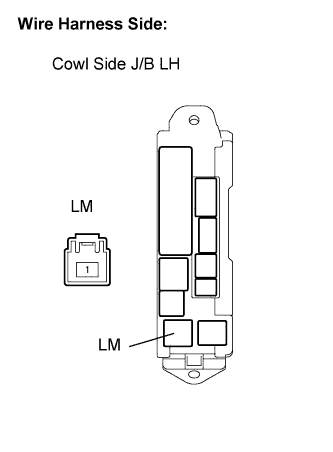
Measure the voltage according to the value(s) in the table below.
- Standard voltage:
Tester Connection
Condition
Specified Condition
LM-1 - Body ground
Always
10 to 14 V
|
|
||||
| OK | |
|
| 9. INSPECT POWER SOURCE CONTROL ECU |
Reconnect the J55 ECU connector.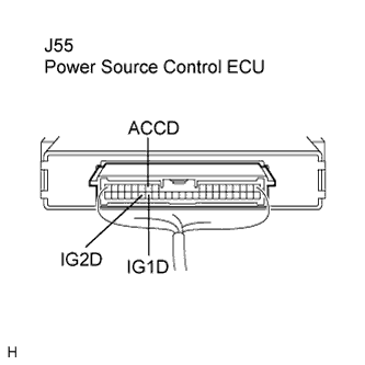
Measure the voltage according to the value(s) in the table below.
- Standard voltage:
Tester Connection (Symbols)
Condition
Specified Condition
J55-34 (IG1D) - Body ground
Engine switch off
Below 1 V
Engine switch on (IG)
8 to 14 V
J55-35 (IG2D) - Body ground
Engine switch off
Below 1 V
Engine switch on (IG)
8 to 14 V
J55-11 (ACCD) - Body ground
Engine switch off
Below 1 V
Engine switch on (ACC)
8 to 14 V
|
|
||||
| OK | ||
 |
||
| ||
| 10. INSPECT ENGINE SWITCH |
Remove the engine switch.
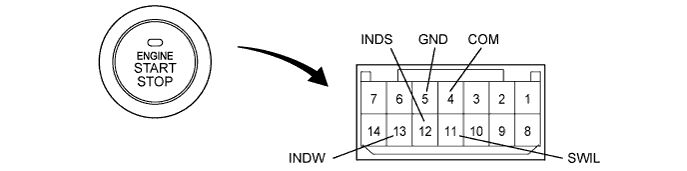
Measure the resistance of the switch.
- Standard resistance:
Tester Connection
Switch Condition
Specified Condition
7 (SS1) - 5 (GND)
Pushed
Below 1 Ω
2 (SS2) - 5 (GND)
Pushed
Below 1 Ω
7 (SS1) - 5 (GND)
Not pushed
10 kΩ or higher
2 (SS2) - 5 (GND)
Not pushed
10 kΩ or higher
|
|
||||
| OK | |
|
| 11. CHECK WIRE HARNESS (POWER SOURCE CONTROL ECU AND BODY GROUND - ENGINE SWITCH) |
Disconnect the J55 ECU connector.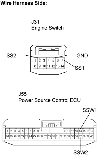
Measure the resistance according to the value(s) in the table below.
- Standard resistance:
Tester Connection (Symbols)
Condition
Specified Condition
J31-7 (SS1) - J55-14 (SSW1)
Always
Below 1 Ω
J31-2 (SS2) - J55-37 (SSW2)
Always
Below 1 Ω
J31-5 (GND) - Body ground
Always
Below 1 Ω
J31-7 (SS1) or J55-14 (SSW1) - Body ground
Always
10 kΩ or higher
J31-2 (SS2) or J55-37 (SSW2) - Body ground
Always
10 kΩ or higher
|
|
||||
| OK | ||
|
||
| ||