Brake Warning Light Remains ON
Circuit diagnosis
DESCRIPTION
The skid control ECU is connected to the combination meter via CAN and multiplex communications.If any of the following is detected, the BRAKE warning light remains on:
- The skid control ECU connector is disconnected from the skid control ECU.
- The brake fluid level is insufficient.
- The parking brake is applied.
- The EBD is defective.
WIRING DIAGRAM
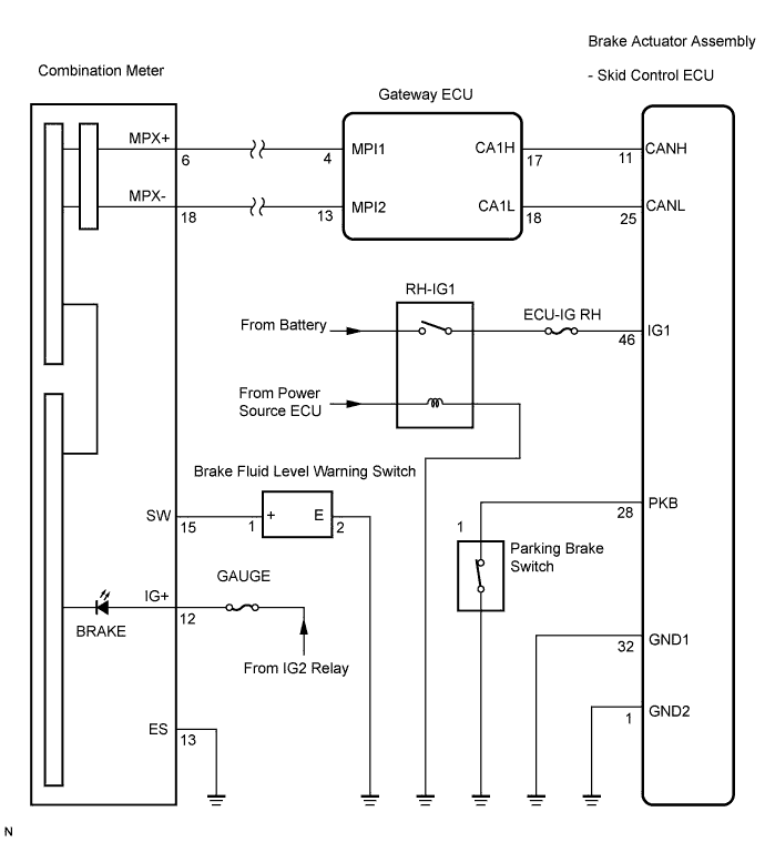

INSPECTION PROCEDURE
- NOTICE:
- When replacing the brake actuator assembly, perform zero point calibration (Click here).
| 1. CHECK CAN COMMUNICATION SYSTEM |

Check if the CAN communication system DTC is output (Click here for LHD, or Click here for RHD).
- Result:
Condition
Proceed to
DTC is not output
A
DTC is output
B
|
|
||||

| A | |
 |
| 2. CHECK MULTIPLEX COMMUNICATION SYSTEM |
Check if the multiplex communication system DTC is output (Click here).
- Result:
Condition
Proceed to
DTC is not output
A
DTC is output
B
|
|
||||
| A | |
|
| 3. CHECK IF SKID CONTROL ECU CONNECTOR IS SECURELY CONNECTED |
Check if the skid control ECU connector is securely connected.
- OK:
- The connector should be securely connected.
|
|
||||
| OK | |
|
| 4. CHECK BATTERY |
Check the battery voltage.
- Standard voltage:
- 11 to 14 V
|
|
||||
| OK | |
|
| 5. INSPECT SKID CONTROL ECU (IG1 TERMINAL) |
Disconnect the skid control ECU connector.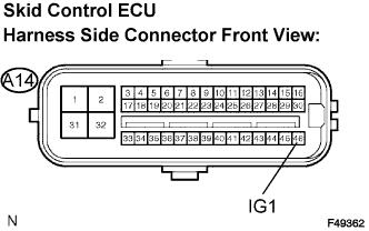
Turn the engine switch on (IG).
Measure the voltage according to the value(s) in the table below.
- Standard voltage:
Tester Connection
Condition
Specified Condition
A14-46 (IG1) - Body ground
Engine switch on (IG)
10 to 14 V
|
|
||||
| OK | |
|
| 6. INSPECT SKID CONTROL ECU (GND TERMINAL) |
Turn the engine switch off.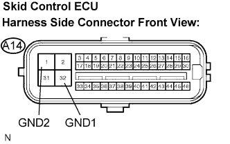
Measure the resistance according to the value(s) in the table below.
- Standard resistance:
Tester Connection
Condition
Specified Condition
A14-32 (GND1) - Body ground
Always
Below 1 Ω
A14-1 (GND2) - Body ground
Always
Below 1 Ω
|
|
||||
| OK | |
|
| 7. INSPECT PARKING BRAKE SWITCH |
Disconnect the parking brake switch connector.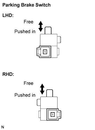
Measure the resistance according to the value(s) in the table below.
- Standard resistance:
Tester Connection
Condition
Specified Condition
1 - Body ground
Parking brake switch ON
(Switch pin free)
Below 1 Ω
1 - Body ground
Parking brake switch OFF
(Switch pin pushed in)
10 kΩ or higher
|
|
||||
| OK | |
|
| 8. CHECK HARNESS AND CONNECTOR (SKID CONTROL ECU - PARKING BRAKE SWITCH) |
Measure the resistance according to the value(s) in the table below.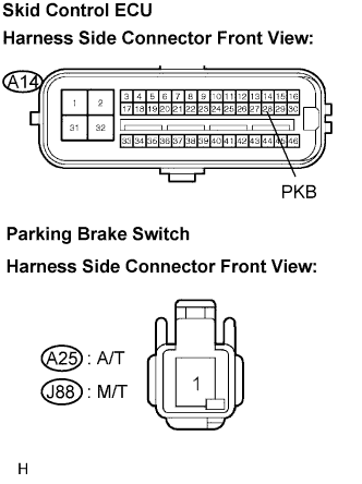
- Standard resistance:
- A/T:
Tester Connection
Condition
Specified Condition
A14-28 (PKB) - A25-1
Always
Below 1 Ω
A14-28 (PKB) - Body ground
Always
10 kΩ or higher
- M/T:
Tester Connection
Condition
Specified Condition
A14-28 (PKB) - J88-1
Always
Below 1 Ω
A14-28 (PKB) - Body ground
Always
10 kΩ or higher
|
|
||||
| OK | |
|
| 9. INSPECT BRAKE FLUID LEVEL WARNING SWITCH |
Remove the reservoir tank cap and strainer.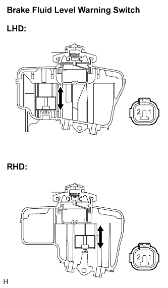
Disconnect the brake fluid level warning switch connector.
Measure the resistance according to the value(s) in the table below.
- HINT:
- A float is placed inside the reservoir. Its position can be changed by increasing/decreasing the level of brake fluid.
- Standard resistance:
Tester Connection
Condition
Specified Condition
1 - 2
Float up (Switch OFF)
1.9 to 2.1 kΩ
1 - 2
Float down (Switch ON)
Below 1 Ω
- HINT:
- If there is no problem after finishing the above check, adjust the brake fluid level to the MAX level.
|
|
||||
| OK | |
|
| 10. CHECK HARNESS AND CONNECTOR (COMBINATION METER - BRAKE FLUID LEVEL WARNING SWITCH) |
Disconnect the combination meter connector.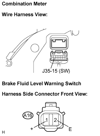
Measure the resistance according to the value(s) in the table below.
- Standard resistance:
Tester Connection
Condition
Specified Condition
J35-15 (SW) - A16-1 (+)
Always
Below 1 Ω
J35-15 (SW) - Body ground
Always
10 kΩ or higher
A16-2 (E) - Body ground
Always
Below 1 Ω
|
|
||||
| OK | |
|
| 11. INSPECT COMBINATION METER ASSEMBLY |
Perform Active Test of the combination meter (meter CPU) using the intelligent tester (Click here).
- OK:
- The BRAKE warning light turns on or off in accordance with the intelligent tester.
- HINT:
- Reinstall the connectors and restore the vehicle to its prior condition before checking the combination meter.
- If troubleshooting has been carried out according to the Problem Symptoms Table, refer back to the table and proceed to the next step before replacing the part (Click here).
- Reinstall the connectors and restore the vehicle to its prior condition before checking the combination meter.
|
|
||||
| OK | ||
 |
||
| ||