Brake Warning Light does not Come ON
Circuit diagnosis
DESCRIPTION
The skid control ECU is connected to the combination meter via CAN and multiplex communications.WIRING DIAGRAM
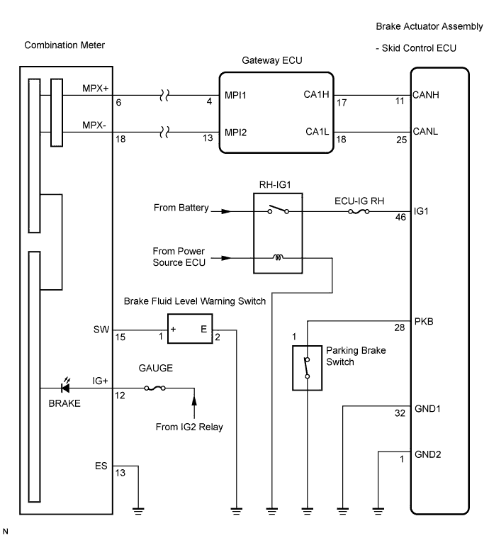

INSPECTION PROCEDURE
- NOTICE:
- When replacing the brake actuator assembly, perform zero point calibration (Click here).
| 1. CHECK CAN COMMUNICATION SYSTEM |

Check if the CAN communication system DTC is output (Click here for LHD, or Click here for RHD).
- Result:
Condition
Proceed to
DTC is not output
A
DTC is output
B
|
|
||||

| A | |
 |
| 2. CHECK MULTIPLEX COMMUNICATION SYSTEM |
Check if the multiplex communication system DTC is output (Click here).
- Result:
Condition
Proceed to
DTC is not output
A
DTC is output
B
|
|
||||
| A | |
|
| 3. CHECK BRAKE WARNING LIGHT |
Disconnect the skid control ECU connector.
Turn the engine switch on (IG).
Check that the BRAKE warning light comes on.
- OK:
- BRAKE warning light comes on.
- HINT:
- If troubleshooting has been carried out according to the Problem Symptoms Table, refer back to the table and proceed to the next step before replacing the part (Click here).
|
|
||||
| NG | |
|
| 4. INSPECT COMBINATION METER ASSEMBLY |
Turn the engine switch off.
Reconnect the skid control ECU connector.
Perform Active Test of the combination meter (meter CPU) using the intelligent tester (Click here).
- OK:
- The BRAKE warning light turns on or off in accordance with the intelligent tester.
- HINT:
- If troubleshooting has been carried out according to the Problem Symptoms Table, refer back to the table and proceed to the next step (Click here).
|
|
||||
| OK | ||
 |
||
| ||