Security Indicator Light Circuit
Circuit diagnosis
DESCRIPTION
Even when the theft deterrent system is in the disarmed state, the security indicator blinks due to a signal output from the immobiliser system. The security indicator blinks continuously due to a continuous signal received from the immobiliser system while in the armed state.The main body ECU RH causes the security indicator to light up or blink only during the arming preparation state and alarm sounding state.
WIRING DIAGRAM
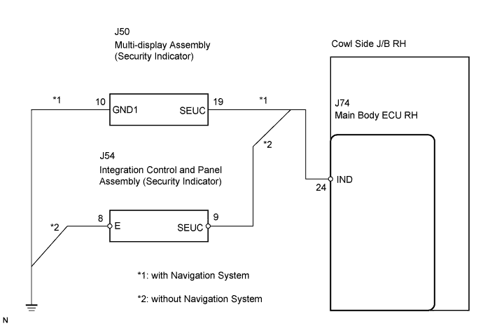

INSPECTION PROCEDURE
| 1. PERFORM ACTIVE TEST BY INTELLIGENT TESTER |

Connect the intelligent tester to the DLC3.
Turn the engine switch on on (IG).
Turn the intelligent tester main switch on.
Select the item below in the Active test and then check that the indicator operates.
Main Body (Main body ECU RH): Item
Test Details
Diagnostic Note
Security Indicator
Security indicator ON/OFF
-
- OK:
- The security indicator light turns on or off correctly when operating it through the intelligent tester.
|
|
||||

| OK | ||
 |
||
| ||
| 2. INSPECT SECURITY INDICATOR |
with navigation system:Check the security indicator.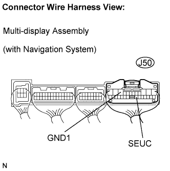
Remove the multi-display.
Apply battery voltage to the terminals of the multi-display and check the lighting condition of the security indicator.
- Standard:
Measurement Condition
Specified Condition
Battery positive (+) → Terminal J50-19 (SEUC)
Battery negative (-) → Terminal J50-10 (GND1)
Lights up
- NOTICE:
- If the positive (+) lead and the negative (-) lead are incorrectly connected, the security indicator will not light up.
- Voltage of more than 12 V will damage the security indicator.
- If the voltage is too low, the security indicator will not light up.
- If the positive (+) lead and the negative (-) lead are incorrectly connected, the security indicator will not light up.
without navigation system:Check the security indicator.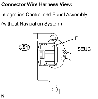
Remove the center cluster integration switch.
Apply battery voltage to the terminals of the center cluster integration switch and check the lighting condition of the security indicator.
- Standard:
Measurement Condition
Specified Condition
Battery positive (+) → Terminal J54-9 (SEUC)
Battery negative(-) → Terminal J54-8 (E)
Lights up
- NOTICE:
- If the positive (+) lead and the negative (-) lead are incorrectly connected, the security indicator will not light up.
- Voltage of more than 12 V will damage the security indicator.
- If the voltage is too low, the security indicator will not light up.
- If the positive (+) lead and the negative (-) lead are incorrectly connected, the security indicator will not light up.
Result Result
Proceed to
NG (w/ LEXUS Navigation System)
A
NG (w/o LEXUS Navigation System)
B
OK
C
|
|
||||
|
|
||||

| C | |
 |
| 3. CHECK HARNESS AND CONNECTOR (MAIN BODY ECU RH - MULTI-DISPLAY OR INTEGRATION CONTROL) |
with navigation system:Check the wire harness between the ECU and multi-display.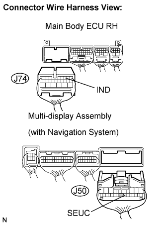
Disconnect the J74 ECU connector and J50 multi-display connector.
Measure the resistance according to the value(s) in the table below.
- Standard resistance:
Symbol (Tester Connection)
Specified Condition
IND (J74-24) - SEUC (J50-19)
Below 1 Ω
IND (J74-24) - Body ground
10 kΩ or higher
without navigation system:Check the wire harness between the ECU and integration switch.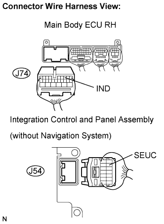
Disconnect the J74 ECU connector and J54 panel connector.
Measure the resistance according to the value(s) in the table below.
- Standard resistance:
Symbol (Tester Connection)
Specified Condition
IND (J74-24) - SEUC (J54-9)
Below 1 Ω
IND (J74-24) - Body ground
10 kΩ or higher
|
|
||||
| OK | |
|
| 4. CHECK HARNESS AND CONNECTOR (MULTI-DISPLAY OR INTEGRATION CONTROL PANEL - BODY GROUND) |
with navigation system:Check the wire harness between the multi-display and the body ground.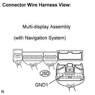
Measure the resistance according to the value(s) in the table below.
- Standard resistance:
Symbol (Tester Connection)
Specified Condition
GND1 (J50-10) - Body ground
Below 1 Ω
without navigation system:Check the wire harness between the integration switch and the body ground.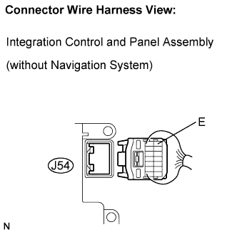
Measure the resistance according to the value(s) in the table below.
- Standard resistance:
Symbol (Tester Connection)
Specified Condition
E (J54-8) - Body ground
Below 1 Ω
|
|
||||
| OK | ||
|
||
| ||