Theft Warning Siren Circuit
Circuit diagnosis
DESCRIPTION
- The theft warning siren has an internal battery. If the vehicle's battery or any of the communication lines is open, the theft warning siren detects it by itself and sounds. Although the theft warning siren usually sounds by receiving a signal from the main body ECU RH, the theft warning siren can sound by its internal battery in case the vehicle's battery is open.
- The main body ECU RH sends an arming signal to the theft warning siren while transferring to the armed state, and it also sends a disarming signal to the siren while switching to the disarmed state. Also, the main body ECU RH can cause the theft warning siren to sound by sending an alarm signal during the alarm sounding state.
WIRING DIAGRAM
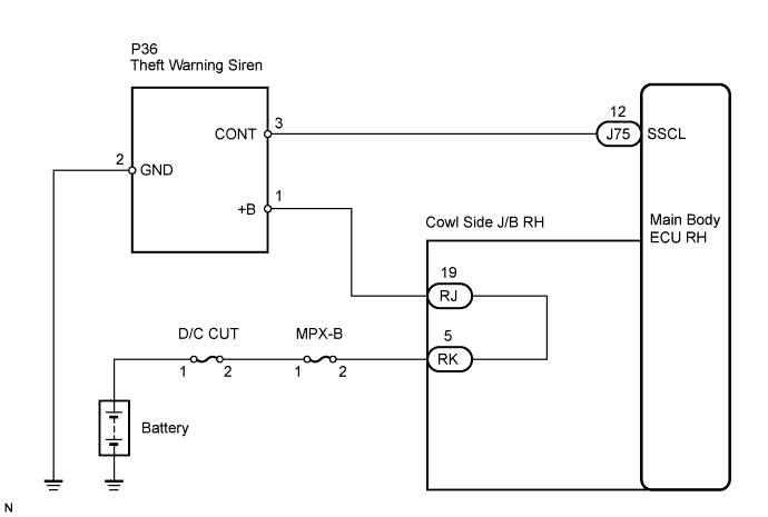

INSPECTION PROCEDURE
| 1. CHECK THEFT WARNING SIREN ASSEMBLY |

Measure the voltage according to the value(s) in the table below.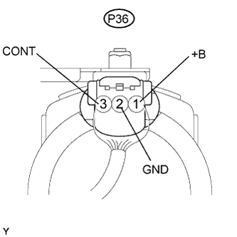
- Standard voltage:
Tester Connection
Condition
Specified Condition
P36-1 (+B) - Body ground
Always
10 to 14 V
P36-2 (GND) - Body ground
Always
Below 1 V
P36-3 (CONT) - Body ground
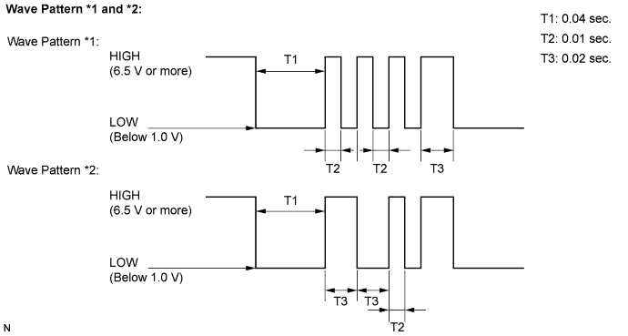
When switched from armed state or arming preparation state to disarmed state (1)
Pulse generation*1
(Using oscilloscope)
When switched from arming preparation state to armed state (2)
Pulse generation*2
(Using oscilloscope)
Normal condition (Except (1) and (2))
Approx. 1.4 V
Wave pattern of the pulse generation *1 and *2
|
|
||||

| OK | ||
 |
||
| ||
| 2. CHECK HARNESS AND CONNECTOR (MAIN BODY ECU RH - THEFT WARNING SIREN) |
Disconnect the J75 ECU and P36 siren connector.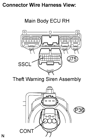
Measure the resistance according to the value(s) in the table below.
- Standard resistance:
Symbol (Tester Connection)
Specified Condition
SSCL (J75-12) - CONT (P36-3)
Below 1 Ω
SSCL (J75-12) - Body ground
10 kΩ or higher
|
|
||||

| OK | |
 |
| 3. CHECK HARNESS AND CONNECTOR (THEFT WARNING SIREN - COWL SIDE J/B RH - BATTERY) |
Disconnect RJ and RK J/B connectors.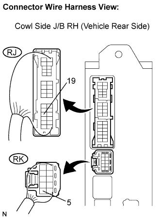
Measure the voltage and resistance according to the value(s) in the table below.
- Standard:
Symbol (Tester Connection)
Specified Condition
+B (P36-1) - RJ-19
Below 1 Ω
+B (P36-1) - Body ground
10 kΩ or higher
RK-5 - Body ground
10 to 14 v
|
|
||||
| OK | |
|
| 4. CHECK HARNESS AND CONNECTOR (THEFT WARNING SIREN - BODY GROUND) |
Disconnect the P36 siren connector.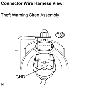
Measure the resistance according to the value(s) in the table below.
- Standard resistance:
Symbol (Tester Connection)
Specified Condition
GND (P36-2) - Body ground
Below 1 Ω
|
|
||||
| OK | ||
|
||
| ||