Reverse Signal Circuit
Circuit diagnosis
DESCRIPTION
The navigation ECU receives a reverse signal from the multi-display and information about the GPS antenna, and then adjusts vehicle position.WIRING DIAGRAM
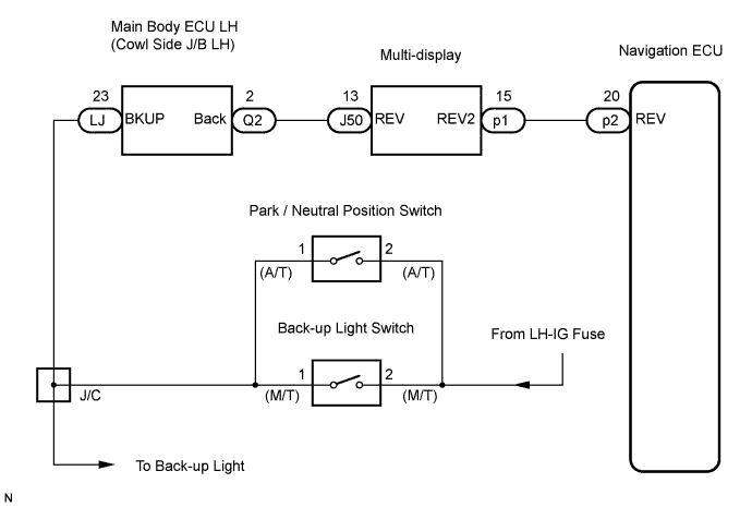

INSPECTION PROCEDURE
| 1. CHECK BACK-UP LIGHT |

Move the shift lever to the R position and check if the back-up lights come on.
- OK:
- The back-up lights come on.
|
|
||||

| OK | |
 |
| 2. CHECK VEHICLE SIGNAL (DISPLAY CHECK MODE) |
Enter the "Display Check" mode (Vehicle Signal Check Mode) (Click here).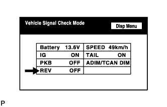
Check that the display changes between ON and OFF according to the shift lever operation (P and R).
- OK:
Shift Lever Position
Display
Reverse
ON
Except Reverse
OFF
- HINT:
- This display is updated once per seconds. As a result, it is normal for the display to lag behind the actual change in the switch.
|
|
||||

| OK | |
|
| 3. CHECK HARNESS AND CONNECTOR (NAVIGATION ECU - MULTI-DISPLAY) |
Disconnect multi-display connector p1 and navigation ECU connector p2.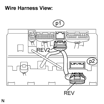
Measure the resistance according to the value(s) in the table below.
- Standard resistance:
Tester Connection
Condition
Specified Condition
REV2 - REV
Always
Below 1 Ω
REV2 - Body ground
Always
10 kΩ or higher
|
|
||||
| OK | |
|
| 4. INSPECT MULTI-DISPLAY |
Reconnect the multi-display connector p1.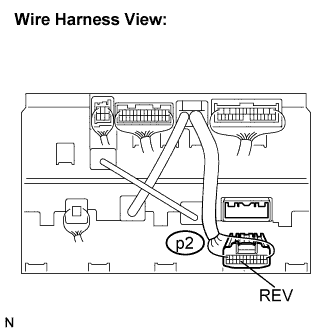
Measure the voltage according to the value(s) in the table below.
- Standard voltage:
Tester Connection
Condition
Specified condition
REV - Body ground
Engine switch is on (IG).
Shift lever is moved to Reverse position.
10 to 14 V
REV - Body ground
Engine switch is on (IG).
Shift lever is moved to any position except Reverse.
Below 1 V
|
|
||||
| OK | ||
 |
||
| ||
| 5. INSPECT MULTI-DISPLAY |
Disconnect the multi-display connector J50.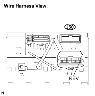
Measure the voltage according to the value(s) in the table below.
- Standard voltage:
Tester Connection
Condition
Specified condition
REV - Body ground
Engine switch is on (IG).
Shift lever is moved to Reverse position.
10 to 14 V
REV - Body ground
Engine switch is on (IG).
Shift lever is moved to any position except Reverse.
Below 1 V
|
|
||||
| NG | |
|
| 6. CHECK HARNESS AND CONNECTOR (MULTI-DISPLAY - COWL SIDE J/B LH) |
Disconnect the multi-display connector J50 and cowl side J/B LH connector Q2.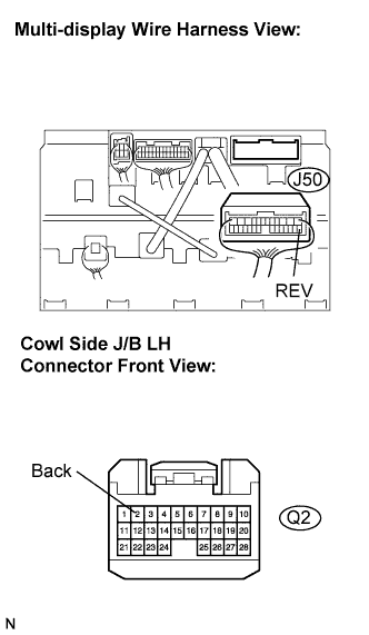
Measure the resistance according to the value(s) in the table below.
- Standard resistance:
Tester Connection
Condition
Specified Condition
REV - Back
Always
Below 1 Ω
REV - Body ground
Always
10 kΩ or higher
|
|
||||
| OK | |
|
| 7. CHECK HARNESS AND CONNECTOR (JUNCTION CONNECTOR - COWL SIDE J/B LH) |
Disconnect the main body ECU LH (cowl side J/B LH) connector LJ.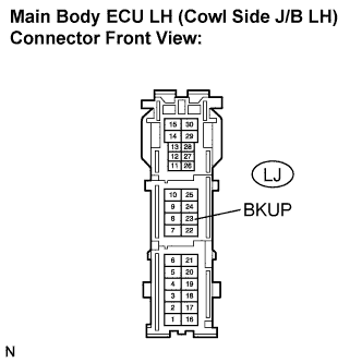
Measure the voltage according to the value(s) in the table below.
- Standard voltage:
Tester Connection
Condition
Specified condition
BKUP - Body ground
Engine switch is on (IG).
Shift lever is moved to Reverse position.
10 to 14 V
BKUP - Body ground
Engine switch is on (IG).
Shift lever is moved to any position except Reverse.
Below 1 V
|
|
||||
| OK | ||
|
||
| ||